1. Introduction
BMXNOM0200 is a Serial Communication Module for Modicon M580 PLC family. The purpose of this article is to introduce You to basic configuration and use of the module. Below, You can see PLC configuration that will be used for this discussion. It contains two NOM0200 modules because all module's data can be arranged/displayed in two different formats. Based on selected format while inserting module into the PLC chassis, there are different methods of handing them. You are going to learn how to extract basic module status and how to send a command to the module as there are few parameters that can be changed dynamically. As I am interested in Modbus mode only, I am going to omit Character mode.
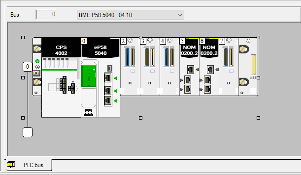
Figure 1 - PLC hardware configuration
2. Configuration
When inserting NOM0200 module in the PLC configuration, at the bottom of window, there is a box where we can select IO data type:
- "Topological" - based on addresses starting with % character
- "Device DDT" - structure (data type)
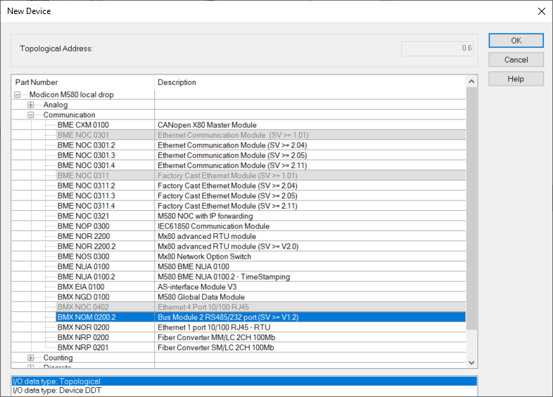
Figure 2 - IO data type selection
3. Data organization
Based on official NOM0200 User Guide I have gathered IO Object related to the module and module’s channel. Please refer to the official documentation for more details as some signals are used only is specific modes or data they hold, can have different meaning depending on configuration.
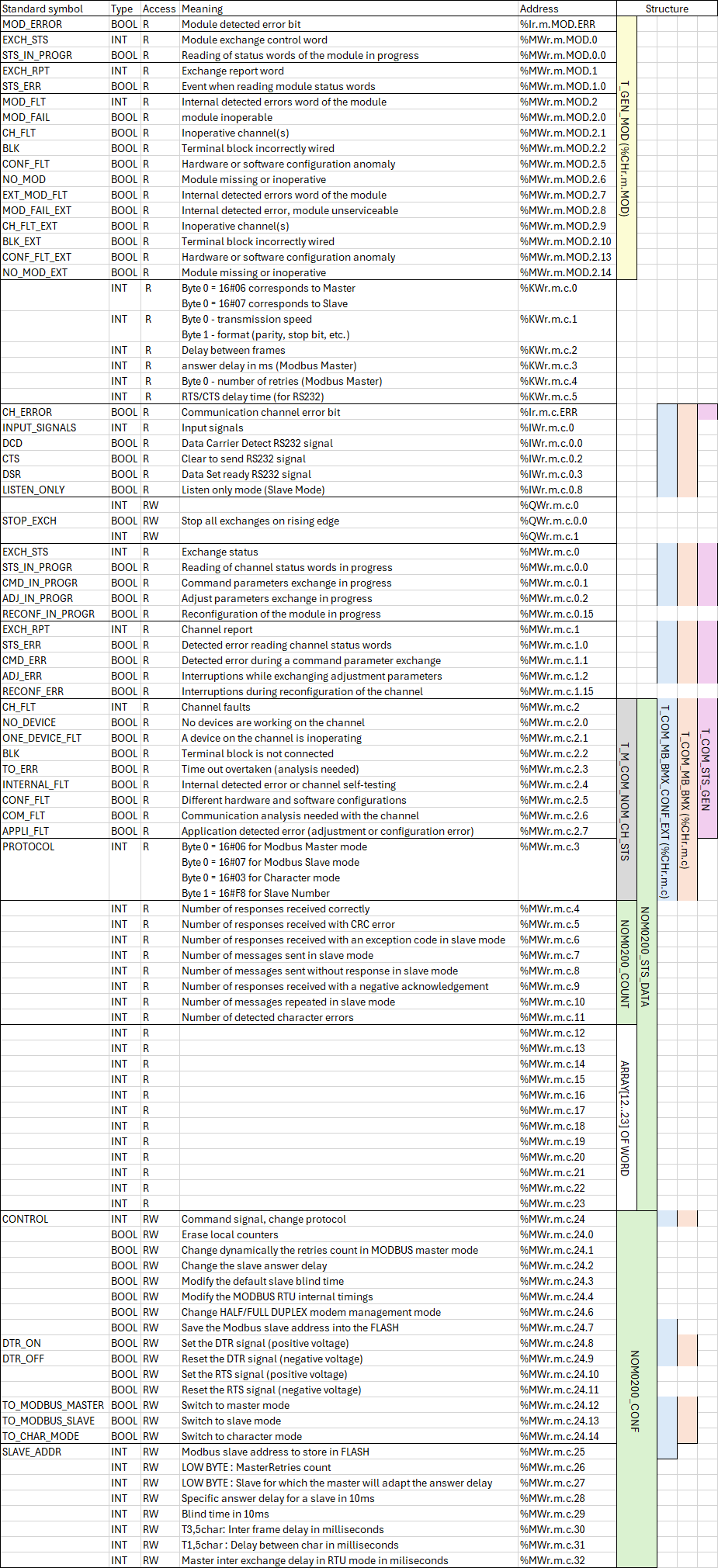
Figure 3 - NOM0200 status and configuration variables
The goal of above table is to map IODDT (structures) to specific addresses and understand from where specific signals come from. As You can see, there is no single structure to cover all addresses. There are several structures provided by SE but at first it not clear which one may be useful in our case. Moreover, there are some data, that are not part of any structure but at some point, in this article, we will need them. Structures marked on light green color in above table are Derived Data Types (custom structures).
The problem I have with above table which, I want to highlight again, is taken from official NOM0200 User Guide are counters (%MWr.m.c.4 - %MWr.m.c.11) captured in NOM0200_COUNT structure. SE says about number of responses received correctly (%MWr.m.c.4) or number of messages sent in slave mode (%MWr.m.c.7) which is confusing once You start using those counters. Both above counters change no matter if the module works as Master or Slave. Which means those counters should be named differently. %MWr.m.c.4 meaning is simply “a number of frames (messages) received”. In case NOM0200 is configured as Modbus Masters, %MWr.m.c.4 is a number of responses received from Modbus Slave. In case NOM0200 is configured as Modbus Slave, %MWr.m.c.4 is a number of requests received from Modbus Master. The same way of thinking can be applied to %MWr.m.c.7 which should be named “a number of frames (messages) sent”. Once I cleared that out, You will understand why elements of MON0200_COUNT structure does not contain elements reflecting exactly what’s in above table.
Please note that based on official User Guide, SE refers to registers with “r.m.c” (for example %IWr.m.c). “r” stands for rack, “m” – for module, “c” – for channel. We have already installed our NOM0200 modules in slot 5 and in slot 6. For each one of them we are going to use only the first channel (index 0) so further on, I will refer to those register based on our PLC hardware configuration (ex. %MW0.5.0 for NON0200 in slot 5).
4. Topological configuration
When no channel is configured, only general module information is available.

Figure 4 - Module data
It is possible to assign a variable in “IO variable creation” section at the left top corner of the window. Once You click on a specific row on a table on the right, configuration tool will suggest variable type. Control Expert provides a data type, T_GEN_MOD, that contains all displayed data (light yellow on Figure 3). We will create a variable named NOM0200_SLOT5_CONF which basically is just a structure. Once created, variable appears in variable list.

Figure 5 - Module variables
Control Expert will not build that configuration as it requires to specify at least one channel. Let’s choose “Modbus Link” as channel “Function” and set basic parameters as displayed below.
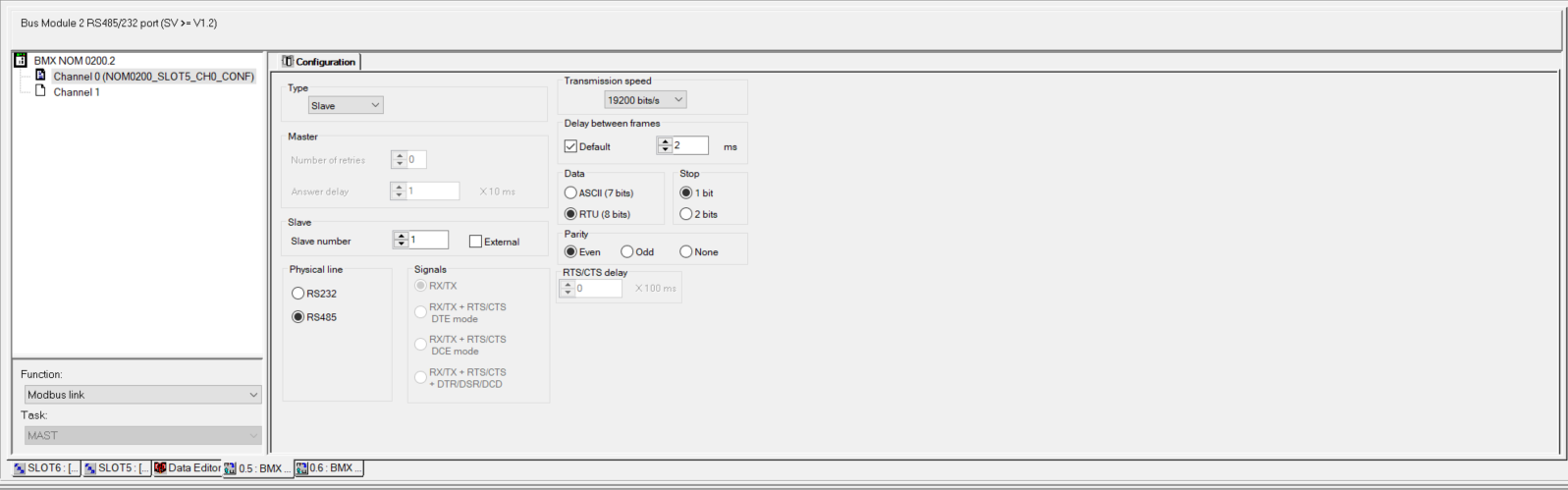
Figure 6 - Channel 0 parameters
For the simplicity of this article, we will configure the module as Slave. We can choose “Slave number” between 1 and 248 here. We also can tick “External” box and choose Slave address as it was saved previously in Flash memory. By default, Slave number saved in flash is 248. Slave number is set back to 248 with firmware upgrade. We can set “Transmission speed”, “Data”, “Stop” and “Parity” only from this place. There is no way to set them dynamically as “Slave number”.
Once channel is configured, we can go back to “IO objects” tab and assign new variable for channel status.
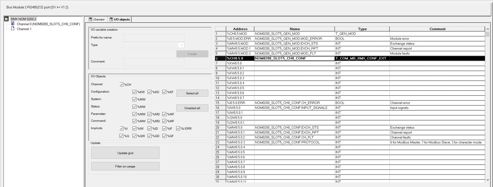
Figure 7 - Channel 0 variable
By clicking on 6th row of the table, again, Control Expert provides available data types. We will select T_COM_MB_BMX_CONF_EXT (light blue on Figure 3) and name our variable NOM0200_SLOT5_CONF. Again, we end up with a variable which basically is a structure. Of course, our variable appears in variable list.
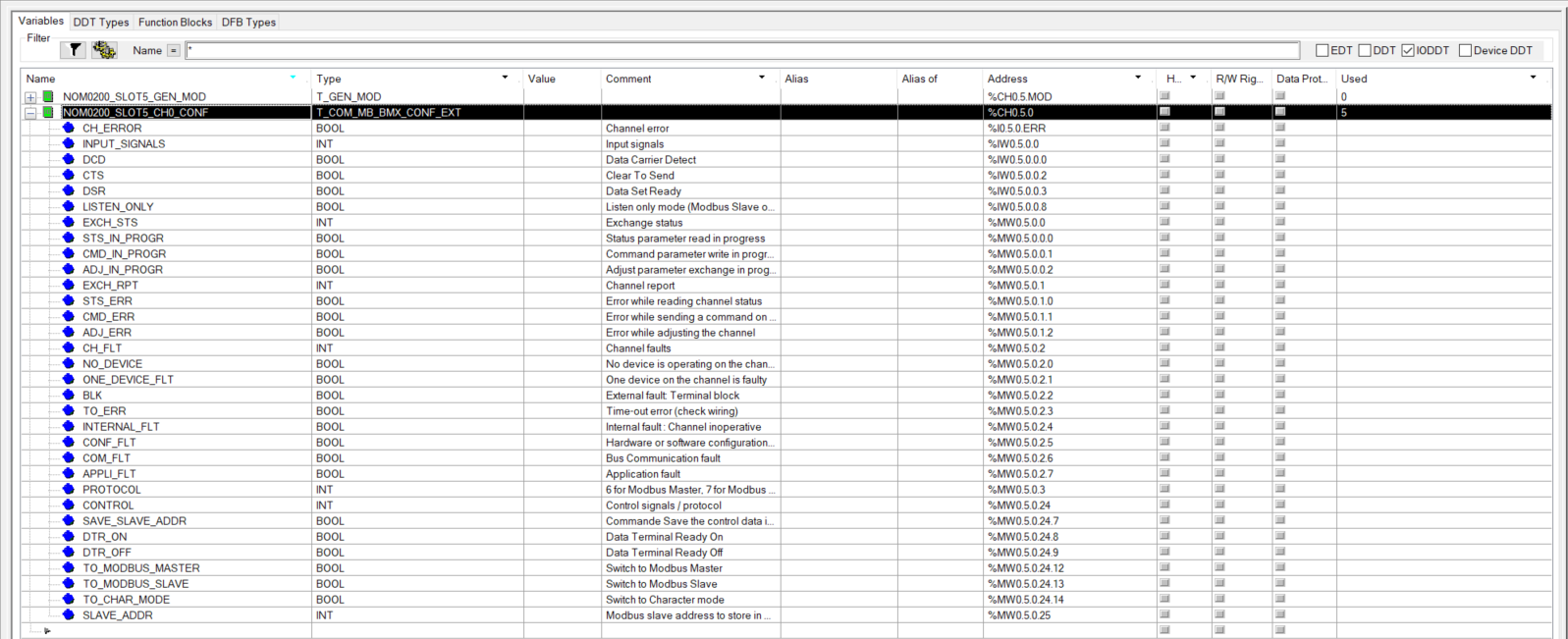
Figure 8 - Channel 0 variables
The problem here is that T_COM_MB_BMX_CONF_EXT contain only part of information available from Figure 7, and You can see it by empty rows on that figure. For the purpose of further examples, we are going to assign additional three registers:
- NOM0200_SLOT5_CH0_REBOOT_VAL (%QW0.5.0)
- NOM0200_SLOT5_CH0_RECEIVED (%MW0.5.0.4)
- NOM0200_SLOT5_CH0_SENT (%MW0.5.0.7)
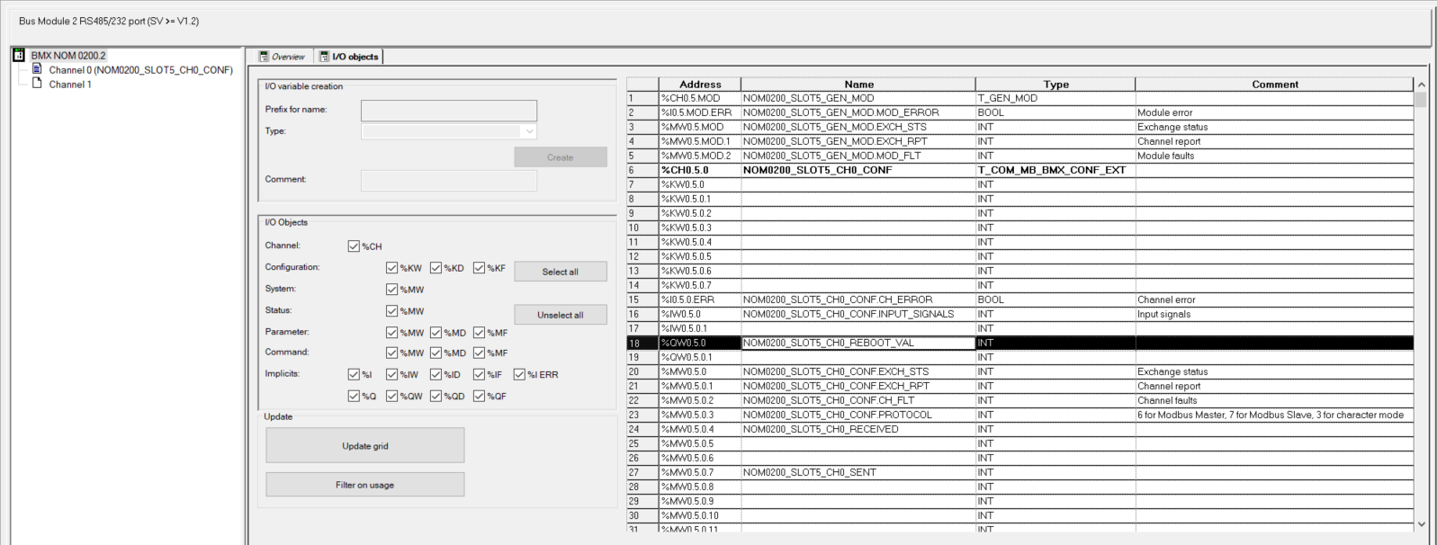
Figure 9 - Channel 0 additional variables
To update NOM0200_SLOT5_CONF data, we need to execute READ_STS function. So, let's create FBD section for NOM0200 communication card located in slot 5 and insert proper code.

Figure 10 - Update %CH0.5.0
4.1. Reset sent/received counters
Once data are refreshed with READ_STS and we have a Modbus Master that is requesting data from our PLC, counters values start increasing. Let’s reset those counters with the command bit %MW0.5.0.24.0. If You take a look at Figure 9 or Figure 3 (light blue), You will notice that this bit is not a part of T_COM_MB_BMX_CONF_EXT structure. There is CONTROL register (%MW0.5.0.24) and we could set the first bit to 1 to reset counters but for clarity of this example let's create our own bit NOM0200_SLOT5_CH0_RESET_COUNTERS with an address of %MW0.5.0.24.0. Now we can perform reset counters action with the following code.
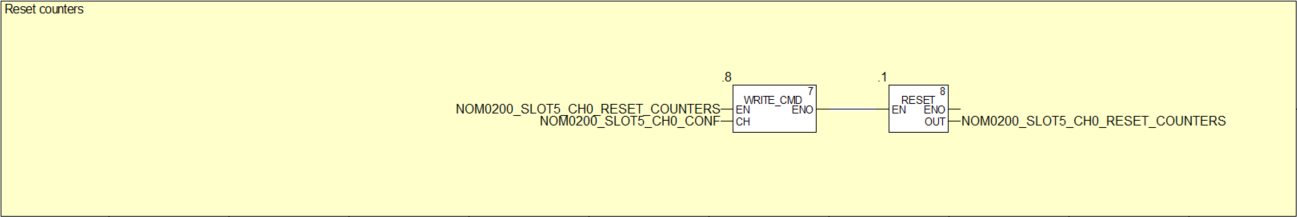
Figure 11 - Reset counter
Please note that we use the NOM0200_SLOT5_CH0_RESET_COUNTERS bit for the command to be executed (assigned to EN input of WRITE_CMD function). We reset NOM0200_SLOT5_CH0_RESET_COUNTERS bit just after WRITE_CMD is enabled because we want to execute WRITE_CMD function only once.
4.2. Change Slave address
If in the channel configuration shown on Figure 6 we ticked “External” box, we can make the module to dynamically change its Slave address. As mentioned earlier, default address is 248. Let’s change it to 13.
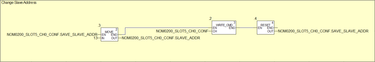
Figure 12 - Change Slave address
Please note that NOM0200_SLOT5_CH0_CONF.SAVE_SLAVE_ADDR not only enables WRITE_CMD but sets address to 13 at the same time. Once WRITE_CMD is executed, nothing changes. NOM0200_SLOT5_CH0_CONF.PROTOCOL doesn’t change (first byte of PROTOCOL register contains Slave address saved in flash). At this point, it is required to reboot the module.
4.3. Reboot
We can reboot NOM0200 module with setting %QW0.5.0.0 to hexadecimal value 16#DEAD (SE R&D shows their sense of humor). No need to WRITE_CMD in this case, simply change specific register value.
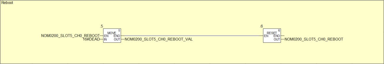
Figure 13 - Reboot NOM0200 module
4.4. Others
There are also other commands. For instance, it is possible to dynamically change NOM0200 from Slave to Master and vice versa. All commands can be found within CONTROL register.
5. Device DDT
When the second option is chosen while inserting NOM0200 module (Device DDT), a variable of T_M_COM_NOM type is created.
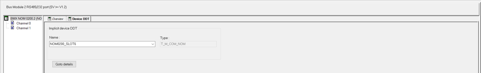
Figure 14 - Module data
NOM0200_SLOT6 holds the following information. Not too many variables comparing to “topological” configuration.
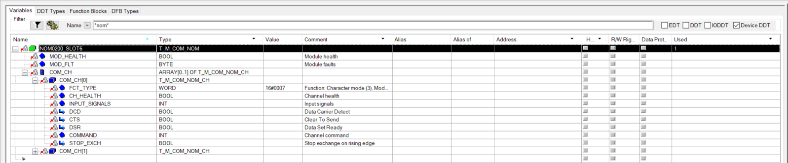
Figure 15 - Module variables
READ_STS is not going to work here. Referring to %CH0.6.0 or %MW0.6.0 is not going to work as well. Fortunately, there is another function that allows us to get most of the information – READ_STS_MX. This function requires some kind of a structure to keep the results that it returns. The problem is that SE don’t provide any data type ready to use. In this case, we will create our own data type – NOM0200_STS_DATA (light green on Figure 3). READ_STS_MX returns 22 registers which are basically data previously identified as registers from %MWr.m.c.2 up to %MWr.m.c.24. To hold first two registers, we can use existing T_M_COM_NOM_CH_STS data type (light gray on Figure 3). Another 8 registers are counters so we will hold them as NOM0200_COUNT structure (light green on Figure 3). Remaining registers are considered as not used and will be kept as an array or words. NOM0200_STS_DATA data type (variable name NOM0200_SLOT6_CH0_Status) is shown below on Figure 16.
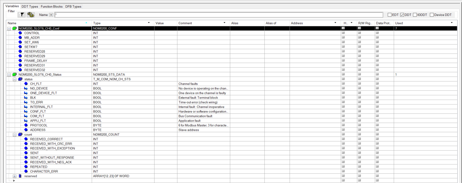
Figure 16 - READ_STS_MX variables
Now we have all variables that we need to call READ_STS_MX. We are going to do it with the following code.
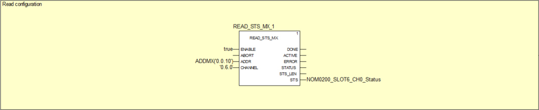
Figure 17 - READ_STS_MX call
READ_STS_MX requires ADDR input to address the module in the local rack and it is done with “0.0.10”. CHANNEL input format is “r.m.c” – rack 0, module 6, channel 0 – “0.6.0”. STS output is 22 register structure.
5.1. Reset sent/received counters
In order to send any command to the module, we need to use WRITE_CMD_MX function block. CMD input of WRITE_CMD can accept indicated in CMD_LEN number or words. The command is basically the same what we saw in addresses from %MWr.m.c.24 to %MWr.m.c.32. There is no natively implemented data type for those registers, so I have created my own structure named NOM0200_CONF (light green on Figure 3).
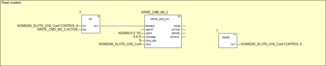
Figure 18 - Reset counter
For simple counters reset, we could just pass one register to CMD input and it would work but some other commands required additional information so, I would like to show a method that would work for all commands.
5.2. Change Slave address
We are going to change Modbus slave address to 15 and save in the module’s flash memory.
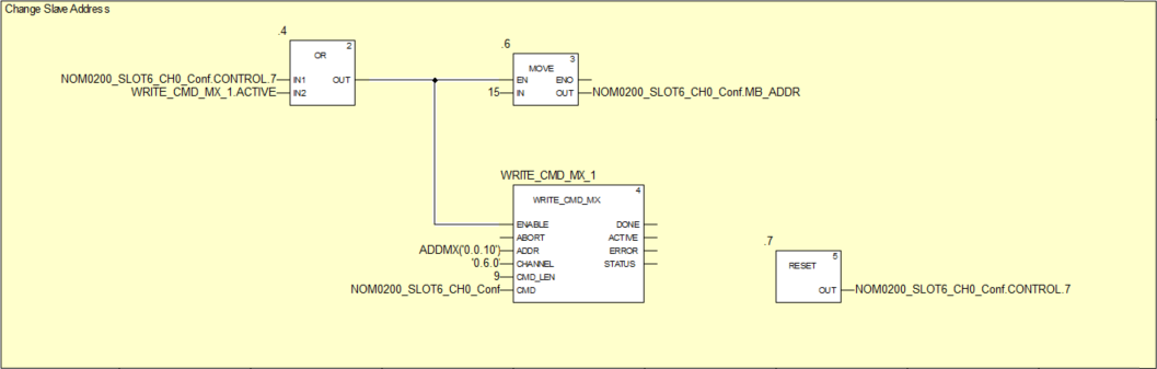
Figure 19 - Change Slave address
As previously, after command execution, module reboot is required.
5.3. Reboot
Reboot command is a part of T_M_COM_NOM (Figure 15). No need to send a command to the module, just set COMMAND register to 16#DEAD. We are going to perform that action using TP function block that will reset register back to 16#0000 after 100ms.
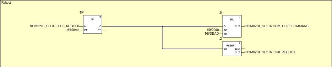
Figure 20 - Reboot NOM0200 module
5.4. Others
There are also other commands. For instance, it is possible to dynamically change NOM0200 from Slave to Master and vice versa by setting proper bit in CONTROL register.
6. Summary
We have covered NOM0200 serial communication module diagnostics and configuration in Slave mode. What I value in Modicon PLC is how easy it is to access PLC memory over Modbus (both RTU and TCP). In our case, it is a matter of configuring basic protocol parameters (baud rate, parity, slave address, etc.). You can connect any Modbus Master (even simulator) to test data exchange. It is very simple.
Things get more complicated in Master mode. There is no internal mechanism of scheduling and requesting data like it is for Modbus TCP - IO Scanner. I will try to cover that part in another article.
Source code here.