1. Introduction
For Modicon PLCs as Quantum, Momentum M340, M580 the easy and transparent way of data exchange over Modbus TCP is done through IO Scanner. Unfortunately, it is limited to Modbus Function Code 3 only. Of course, there is a way to send Modbus request with other function codes, but to do that, we need to develop our own piece of code and utilize READ_VAR, WRITE_VAT or DATA_EXCH function from the standard library.
We can intentionally retain from using IO Scanner or we may be forced to do this by the number of data our system has to process. Communication modules of M580 family, BME NOC 03x1 have limited memory capacity.
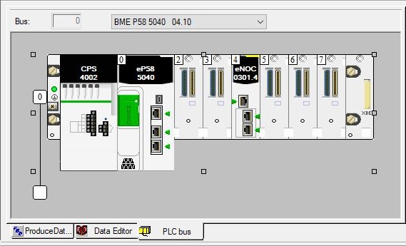
BME NOC 0301 and BME NOC 0321 maximum input sizes are: 3867 WORD and 1819 WORD. Maximum output sizes are: 3871 WORD and 1823 WORD. If we require more, the easiest solution it to add another NOC modules but what if we reach the limit of communication modules in the rack? Starting from Control Expert v15, it is possible to install maximum 4 NOC communication modules which gives us maximum 15468 of input words and 7276 of output words. It still may not be enough for bigger systems. I would like to discuss one of the possible solutions for that problem – DATA_EXCH function. We are going to use three BME P58 5040 PLCs here. First PLC will be a data producer where we are going to create 350 elements array holding data available to read by other PLC. Second PLC will be a data producer as well where we are going to create 6 structures of 17 words each. They will be placed one after another so from the outside they can be read with single request of 102 registers. Third PLC will be data consumer that will read data from both producers. All PLCs will be equipped with BME NOC0301 communication module in slot 4 through which all the traffic will be handled.
2. Concept
The idea is to create a code that is scalable so it can be used in different situations. The PLC should be able to obtain data from different sources (from different Slaves). There will be differences in the quantity of polls for different sources. Based on assumptions from introduction, 350 registers would require 3 requests. 102 registers would require only 1 request.
For now, we are considering only reading data. From the Modbus protocol point of view, we are going to prepare ourselves to execute Function Codes 3. What we need (excluding one byte of ID) is 5 elements array of byte to hold the request and 252 elements array to hold the response. We would like to keep our data organized in a clear way so we can easily match the response to the request. We are going to create data type (structure) of two mentioned above arrays that covers one poll. We are going to name that structure “MODBUS_POLL”. We may have different number of polls so eventually, we are going to create 3 elements array of MODBUS_POLL for the first source and one element array of MODBUS_POLL for the second.
We are going to send all request one right after another. With the time delay between the last request and the first one.
3. Implementation
PLC program for the data Consumer will contain two independent sections. One dedicated for Producer 1, second for Producer 2. Each section will be divided for three parts:
- request creation,
- data exchange where request will be send and response received,
- response extraction where data will be structured to desired form.
3.2 DATA_EXCH
DATA_EXCH function from the standard library will be used.

Where:
- GEST input/output parameter is four elements array holding communication management data. User needs to set last two elements for the timeout and length of data. First two elements hold exchange number, activity status and operation/communication report,
- ADR input allows to specify through which module communication should be handled, destination address and protocol used (Modbus TCP in this case),
- TYP value is always 1 for M580 controllers,
- EMIS input is an array holding Modbus request,
- RECP output is an array holding Modbus response.
Unfortunately, EMIS and RECP do not accept array of bytes for request and response but array of integers. MODBUS_POLL structure is going to change to hold 3 elements array of integers for the request and 126 elements array of integers for the response. Another thing to pay attention to is that they operate on a specific order of bytes.
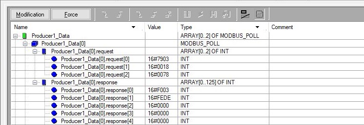
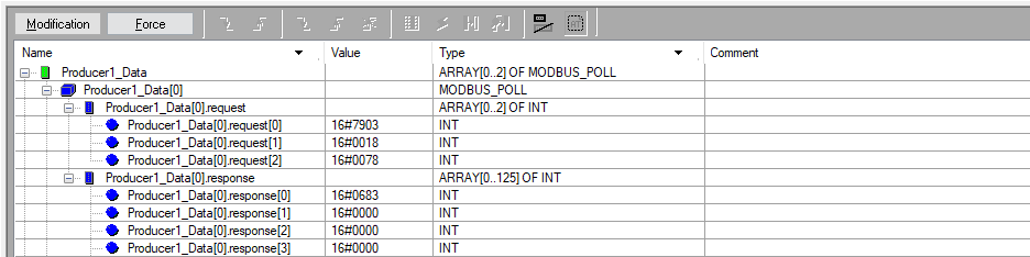
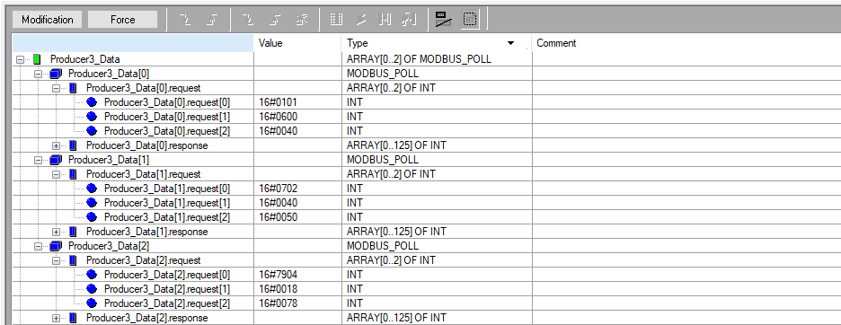
Here is an example of Modbus request Function Code 3, reading 120 registers from 31000 address in hexadecimal:
Modbus request frame: 03 79 18 00 78
DATA_EXCH.EMIS[0]: 79 03
DATA_EXCH.EMIS[1]: 00 18
DATA_EXCH.EMIS[2]: 00 78
The response is:
DATA_EXCH.RECP[0]: F0 03
DATA_EXCH.RECP[1]: FE DE
DATA_EXCH.RECP[2]: 00 00
…
DATA_EXCH.RECP[125]: 00 00
Modbus response frame: 03 F0 DE FE 00 00 … 00 00
Where 240 is the quantity of bytes holding data from the slave. -8450 is the first obtained register value.
3.3 Supporting Derived Function Blocks
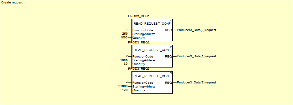
3.3.1 Request
To build requests table, we have created another Derived Function Block executing the translation described in example above. This block is specifically created for Function Code 3 and its name is FC3_REQUEST_CONF. As inputs it takes “starting address” and “quantity”. As output, it provides 3 elements array of integers that is going to be assigned to DATA_EXCH.EMIS input further.
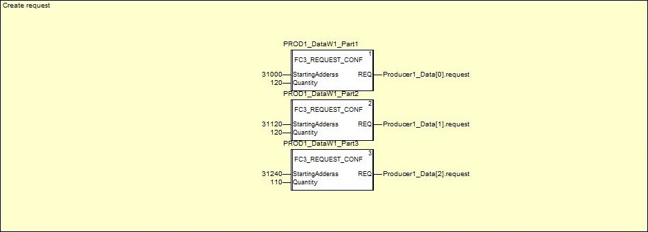

There are no any limits for the values assigned to the inputs. Please keep in mind that, based on Modbus protocol specification, Quantity for Modbus Function Code 3 must be a value between 1 and 125 (including).
3.3.2 Response
We need to swap bytes within the response array, so let’s structure them at the same time. DATA_STRUCTURIZE_350 will be used to build 350 elements array obtained from the first source.

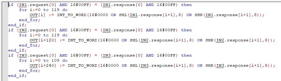
DATA_STRUCTURIZE_6x17 will be used to build 6 arrays if 17 words each.

3.3.3 Data exchange
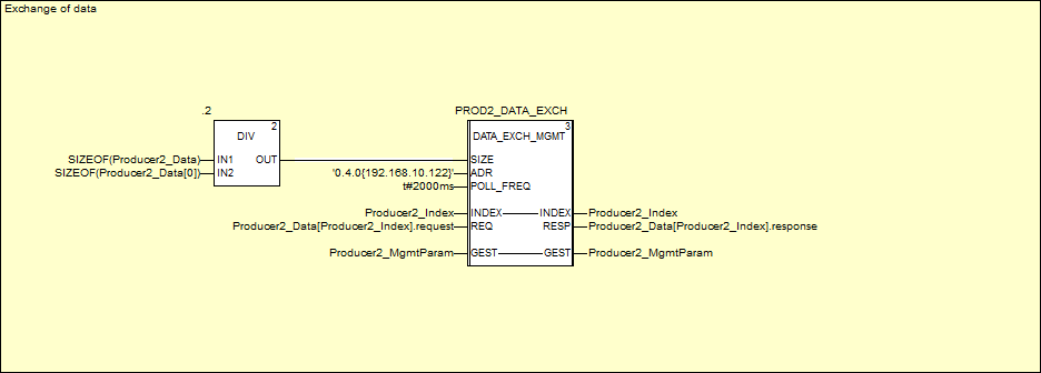
Array of MODBUS_POLL will hold all requests/responses required for the specific Slave. Our goal is to have one Derived Function Block, let’s name it DATA_EXCH_MGMT, that manages all data exchange between Master and Slave. It should allow to manage different Slaves, which basically means different number of polls – different sizes of MODBUS_POLL arrays.
The content of MODBUS_POLL array should be passed to DATA_EXCH_MGMT. The idea was to pass a pointer to the first element of MODBUS_POLL array and loop through the array within the DATA_EXCH_MGMT. The problem is that Control Expert has its limitations, and it doesn’t support pointers. We can’t pass whole MODBUS_POLL array because input requires to specify data type and the type is an array that size may change, so we would not end up with only one DFB. In this case, let’s take the index, used to loop through the array, out of the DATA_EXCH_MGMT but increment it inside DATA_EXCH_MGMT. Inde will be specified as input/output parameter.
Using the index, we can select which element of MODBUS_POLL array to pass to/from DATA_EXCH_MGMT.
POLL_FREQ input specifies how often to poll for data.
ADR input specifies through which module (through which slot) to initiate the communication and with what Slave (with what IP address).
SIZE input could have been explicitly assigned with a number representing the size of MODBUS_POLL array but we don’t want to remember to update it every time the size of MODBUS_POLL array changes. Dividing the size of MODBUS_POLL array by the size of its element, results in number of elements used by MODBUS_POLL array.
Why do we take GEST array out of my DFB? Well… There are some problems with communication functions like DATA_EXCH, READ_VAR, WRITE_VAR inserted in DFB. In my case, the DATA_EXCH didn’t work correctly until I took GEST array into the main program and assigned global variable for it. Except my experience, and advice from one of my friends working closely with Schneider Electric company, I have never been able to find that information in the official manual. Anyway, whenever I think of using communication function inside DFB, I take GEST array out of it.
Now, let’s take a closer look at what’s inside DATA_EXCH_MGMT.
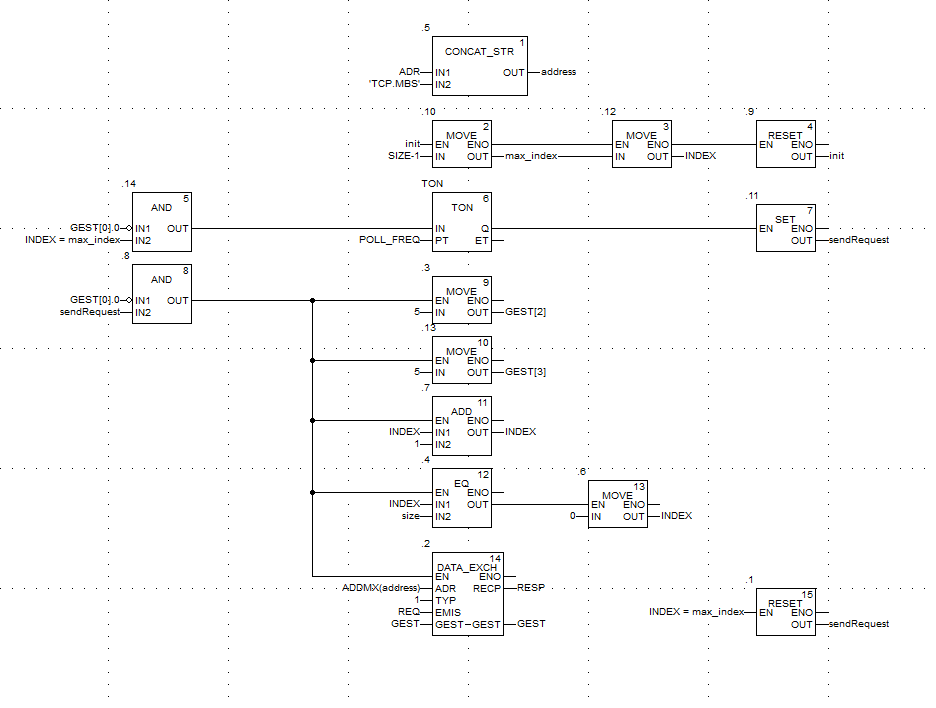
First, we need to add ‘MBS.TCP’ suffix to the address. If we don’t do it, eventually DATA_EXCH function will not work correctly even if it seems exchanging data normally at first.
Second, index is being initialized to the value of last element of the array so the whole program starts with the first request.
Timer TON is started once activity bit of DATA_EXCH function is complete and when the index value is the max index of the array. It creates a time gap after the program looped through all elements of MODBUS_POLL array.
GEST[0].0 is activity bit of DATA_EXCH function. When it changes state to zero, the following actions are taken:
- GEST[2] is assigned with 5 – 500ms timeout.
- GEST[3] is assigned with 5 – quantity of bytes to send. In my case it is always 5 (because of Modbus Function Codes 3).
- index is incremented by one,
- index is reset to zero if it goes above to MODBUS_POLL array size,
- DATA_EXCH is called.
With DATA_EXCH call, activity bit (GEST[0].0) is set to one. You can think of it as of one controller cycle length pulse.
Upon completion of DATA_EXCH function DATA_EXCH.RECP array is filled with data and GEST[3] is override with numbers of bytes received.
4. Summary
4.1 Advantages and disadvantages
As every solution, this one also has advantages and disadvantages. We implemented above logic to increase amount of data obtained by the communication module, but we also paid the price. Data must be obtained one after another. It means that refreshment of data becomes slower and slower with increasing number of requests. The goal is to find a balance. I would leave critical data on DTM and use above solution to request remaining one. As DTM is more comfortable to use, I would also leave requests of relatively low size and the one in which data need to be assigned individually. I would definitely consider passing big tables with above solutions (exactly like we did in this example – 350 registers).
4.2 Communication status
Another concern about DATA_EXCH is communication failure status. GEST[1] holds operation and communication report and I expected that if I don’t have a Slave of specific IP in my network, I would be informed by that in GEST[1]. I was really surprised when I saw that no such status is generated. Instead, inside DATA_EXCH.RECP, I received (HEX): 0683. Which is exception for Function Code 3 with code 6. This kind of exception are generated by the Slave so the response is like I would have a Slave connected but in fact, I don’t. It was so strange to me that I contacted Schneider Electric technical support. Unfortunately, I didn’t get any clear answer. It seems they didn’t accept it as a bug. They also didn’t really explain mechanism behind DATA_EXCH and why they handle communication failure in such strange way.
4.3 Request extension
FC3_REQUEST_CONF is DFB that You can use straight away. It does not need to be changed. As Modbus Function Codes 1, 2, 3 and 4 have the same request frame structure, You can easily extend the code to read Function Codes 1,2 and 4 as well.
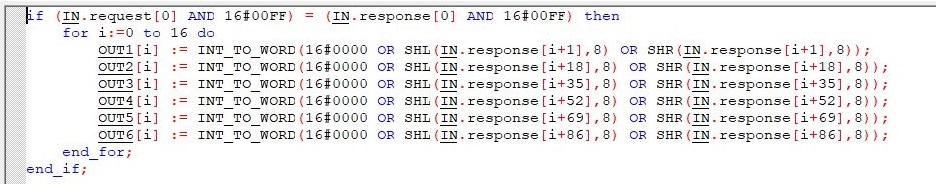
Add one more input named Function Code and assign it as the first byte of array. Remember that for Function Code 3, the maximum registers quantity is 125 and only one byte needs to be managed. Function Codes 1 and 2 can go up to 2000 bits. You need to manage two bytes as Quantity input but in the original DFB one byte is fixed to zero. So another small adjustment is required. The code looks like below.

And to prove correct data assignment:
4.4 Response management
DATA_STRUCTURIZE_350 and DATA_STRUCTURIZE_6x17 Derived Function Block demonstrate one way of assembling data from DATA_EXCH response. They are specific to my needs and most likely You will never need them. You will need Your own DFB to manage Your own data.
4.5 Function Codes 5, 6, 15, 16
What about Function Codes that allow to write data to Slave? From my experience, in system I managed, writing is usually on demand. It also may take a different form like, writing just a bit command or setting a time in IDE and writing 4 registers at once. It means that request table size will vary and 3 elements array on integer will not be enough. I believe it will required dedicated code and dedicated article explaining it.
Source code for: