1. Introduction
NOM0200 and Modicon controllers, M580 in this case, are perfect to be a Modbus Slave. Just simple configuration of communication parameters is required – baud rate, quantity of data bit (7 or 8), parity and of course slave address. That’s it. If You controller addresses are available, all communication will be handled automatically. You just refer to the specific address – yes, it really is that simple.
The difficulties appear when You want to turn NOM0200 in Master mode. For Modbus TCP, used with NOC03x1 module, there is a built-in tool called IO Scanner. See Modicon PLCs -> Ethernet Communication if You haven’t already. It allows You to configure request at will. Unfortunately, there is no such tool for Modbus RTU. Things get complicated here because serial port, as the name states, is serial. You can’t send several requests and wait for an answer. You need to send them one by one, waiting for the response, managing errors and timeout. But of course, it is obvious if You are familiar with Modbus RTU protocol standard.
Control Expert, IDE used for Modicon PLCs, contains function blocks that can be used to send data on serial line and receive response. These are READ_VAR, WRITE_VAR, DATA_EXCH. They are easy to use. The real challenge starts when You need to obtain data from different registers of different devices. Regardless, whatever You have different devices to talk to or all of them are of the same kind, You end up with multiple frames to handle.
2. Objectives
Build Modbus Master that:
- handles basic function codes: FC1,2,3,4,5,6,15,16,
- "Device DDT" - structure (data type)
- manages frame retires,
- collects diagnostics,
- schedules frames by the polling time - how frequent specific request should be send,
- sends frames one after another (waits for the response or timeout before sending next frame),
- avoid using any kind of buffer for scheduling to avoid problems with overflowing it,
- aggregates frames within a model (basically to have one function block per device),
- allows duplicating devices easily (in a result, application engineer should not write the code for every device but use a model where he assigns basic parameters),
- make the code in non-blocking manner (controller cycle should not be delayed because we are waiting for the response).
So, the idea is not only to write Modbus Master but also do it in way that it would look more like configuration than pure coding.
Regarding non-blocking code, I would like to clarify that, except for CodeSys, I have never seen any industrial controller with blocking functions. Controllers code in general is executed inside infinite loop. One loop though all the program is called a cycle. If cycle time exceeds specific time, PLC stops (usually seen on PLCs) or reboots (usually seen on microcontrollers). CodeSys has some communication related functions that could block the program execution cycle and wait for an event like data received. Of course, there are some walk arounds for most of those functions and in CodeSys it is possible to disable monitoring of cycle time. This is a topic for separate article. Here I only want to highlight that we need to be aware that PLC cycle needs to go on regardless of our code.
3. System configuration
Let’s build Modbus Master for below configuration.
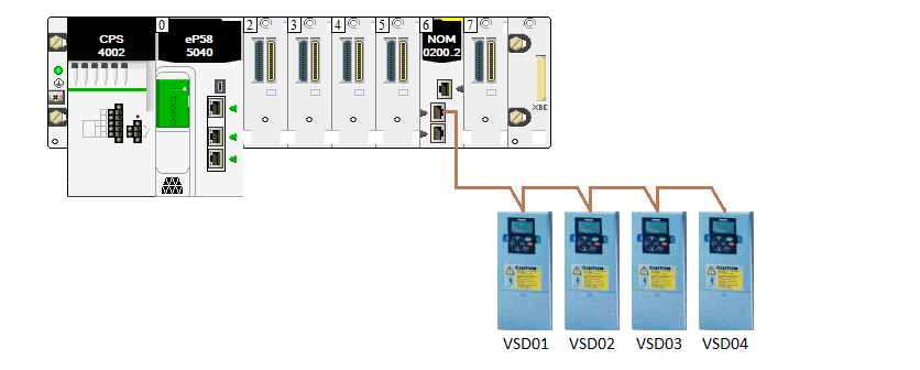
Figure 1 - System configuration
Four Vacon VSDs will be connected to COM PORT 0 of NOM0200 module placed in SLOT 6 of 8 slot chassis with M580 PLC in slot 0.
From VSD we need to:
- Read several inputs that are located on Modbus address 14 and 15,
- Read several measurements that are located on Modbus address 2100 – 2110,
- Write start/stop command located on Modbus address 2000,
- Set desired speed located on Modbus address 2002.
Communication parameters: 19200, 8, 1, even.
Modbus Slave addresses are 11, 12, 13 and 14.
4. Concept
We are going to use DATA_EXCH because regardless the function code, it is possible to pass data as an array. There will be only one DATA_EXCH block per COM PORT.
We are going to poll for inputs (register 14 and 15) every second and for measurement (register 2100-2110) every three seconds. Why do I speak about inputs that are located on registers 14 and 15? Why not to use FC2 to read inputs? In this case, all inputs statuses are placed in register 14 and 15 and they are available via FC3. It all depends on Your device. Open user manual of Your device, find whatever information You are interested in and see how (with which function code) You can get it. In my case, both inputs and measurements like voltage, current, torque, etc. can be accessed with FC3.
Let’s get back to polling time. Inputs every second. Measurements every three seconds. It means that if all my VSDs are responding normally, if my serial line is fine, I expect that ratio of inputs to measurements is 3:1.
Each request will go with separate function block. Each function block will be indexed so we can loop through all of them. Once activation condition is met for a block, this block will take a line. It will also indicate to the program that line is being used so no other block can use it even if its activation condition is met. Once the block that is currently using the line releases it, whatever on correct response or not, next block with activation condition met will take the line. To illustrate that mechanism let’s assume that data exchange between Modbus and Slave takes 200ms and see below diagram.

Figure 2 - Sequence of block execution
Read the diagram like a book. From left to right. From up to down. Please note that while several blocks are ready, priority has the one which is just next after the block currently using serial line. Example: in the 3.0s block BLK7 finishes using the line. At that point of time, blocks BLK2, BLK4, BLK6 and BLK8 are ready to take a line. The program is currently leaving block BLK7 and the next block in order is BLK8 and it is BLK8 which is going to use the line next.
Because we are planning to use different function codes, we need to consider creating different block activation ways.
5. Implementation
5.1 NOM0200_SLOT6_PORT0 section
Let’s start with overview of the section related to COM PORT 0 (NOM0200 slot 6) and polling schedule initialization. We are going to configure two variables, “index” and “currentStep” that will help us looping through the program section and identify at what point of the program we are.
Each polling block needs have unique number. It could have been assigned statically by hand, but I am planning to use this Modbus Master in big system where I expect modifications over time, and I don’t want to waste time and risk possible typing mistake for manually assigning a number for each block. And this is why I will do it automatically utilizing “index” variable.
The other value, “currentStep” will be used to loop through all the block and its value will change depending on block availability for communication.

Figure 3 - Index initialization
At the beginning of the section, “currentStep” is set to 1 if it equals “index”. When PLC starts for the first time both “currentStep” and “index” are 0 so “currentStep” is set to 1. After first PLC cycle, “index” value is the sum of all blocks used in this section. “currentStep” is incremented every time data between Master and Slave are exchanged. It also changes when no block is ready to take a line. “index” is set to 1 – always.

Figure 4 - Index initialization logic
Next part of the code is related to VSDs. Here You can clearly see that one device is represented with one function block which simplifies coding. We will dive into detail of VACON_VSD function block in a moment. There are also VACON_VSD_SOURE_SELECT function blocks that allow to simulate data from Vacon. This functionality could have been included in VACON_VSD block but I decided to separate data simulation from data obtainment process.
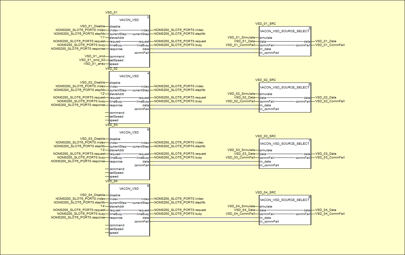
Figure 5 - VACON_VSD function block
The last past of the code is port management.

Figure 6 - COM PORT management
From within EXCHANGE_OVER_SERIAL_LINE function block data are being sent and received. As mentioned earlier, it is based on DATA_EXCH block and this topic was discussed already in Modicon PLCs -> Ethernet Communication -> Alternatives.
5.2 VACON_VSD function block
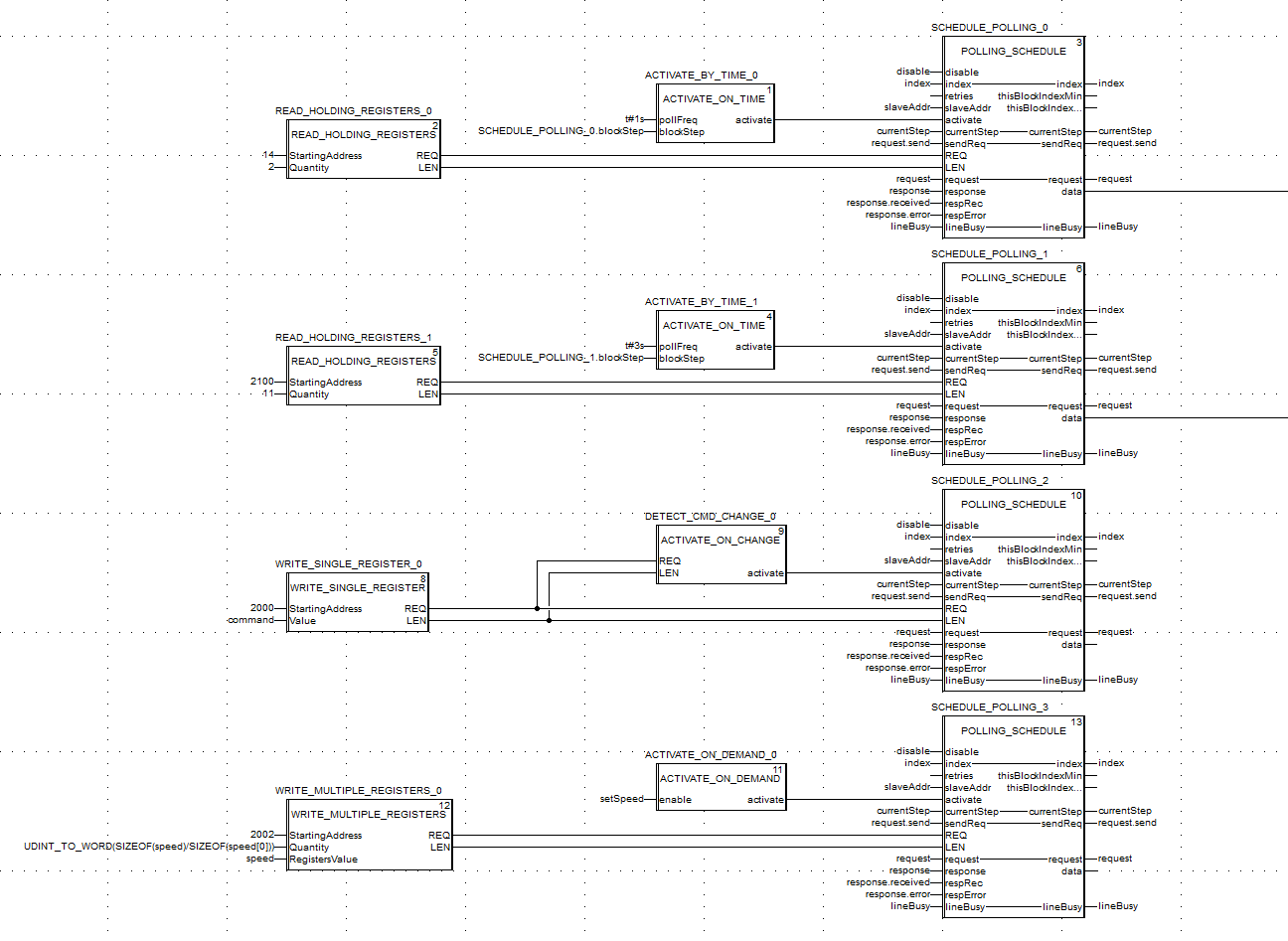
Figure 7 - VACON_VSD detailed logic
There are four frames configured for VSD. A frame is represented with POLLING_SCHEDULE function block. Combination of activation block and frame is required for POLLING_SCHEDULE to work. Based on information from System Configuration discussed above, You can easily see where we read inputs and measurements (first two POLLING_SCHEDULE blocks).
Third and fourth block is something that I need to adopt for my specific case. Vacon VSD uses register 2000 for command and it is customized. I need to set bit number 3 to true to stop it. I need to set bit number 4 to start it. After setting start/stop bit, VSD doesn’t reset it. Which basically means I need to send two frames to start/stop. This is the reason why I chose to use ACTIVATE_ON_CHANGE and take the “command” input of VACON_VSD function block. You might think that it may not be necessary to set start/stop bit back to zero, but You need to take into consideration that VSD can be stopped on fault or be stopped by other system like VSD. If I simply send start command, don’t reset it and my VSD stops on fault, command register is still set. So, sending another start command results with no action because VSD doesn’t see bit change. You would need to send stop command first and start again which is not normal.
The last frame is something done for the purpose of this example. I intentionally used function code 16. In fact, in my system, I do not use it like that but the idea behind this code was to show that operator could set speed register manually to specific value and then send it to VSD with dedicated button.
5.3 ACTIVATE_ON_TIME function block
This block uses TON timer. POLLING_SCHEDULE must be at the specific moment for the timer to start counting. Condition (blockStep=10) indicates the moment when previous request finished. “not scanRate.Q” is a trick for the timer to reset itself.

Figure 8 - ACTIVATE_ON_TIME function block
5.4 ACTIVATE_ON_CHANGE function block
This is more complicated. We need to comapre frame with previously sent one. We don’t want to send anything when PLC is set to RUN mode for the first time. Request was build earlier but array containing previous request is still filled with zeros. On first scan we simply rewrite request content to previous request variable “cmdPrev”.
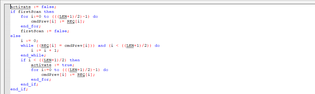
Figure 9 - ACTIVATE_ON_CHANGE function block
To compare requests, we need to compare every array index one by one. I could have done it in FOR loop, but I used WHILE loop to find the first different element and check whatever the first different element is not the maximum array size. If requests are the same, both FOR and WHILE loop would go through all elements. If they are different, WHILE will stop on the first different element. Keep in mind that we are operating on an array of integers required by DATA_EXCH but we really work on bytes. Length indicates quantity of bytes, and this is the reason why we check until half of the length. Activation condition is set when we left WHILE loop before reaching the end of array which means arrays differs.
5.5 ACTIVATE_ON_DEMAND function block
To activate on demand, I simply use R_TRIG – rising edge of activation bit. I want to avoid situations to send command two times. First when enable bit goes from 0 to 1. Second when enable bit goes from 1 to 0. Keep that in mind when assigning activation logic out of VACON_VSD function block.

Figure 10 - ACTIVATE_ON_DEMAND function block
5.6 POLLING_SCHEDULE function block
This is the heart of the program which has been split for 5 parts.
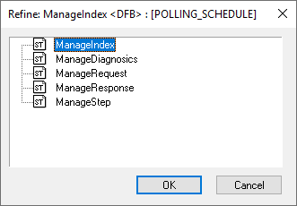
Figure 11 - POLLING_SCHEDULE function block
I would like to highlight that the order of those section is not random. ManageIndex must go first because it is refreshed with every PLC cycle and then used in other sections. ManageDiagnostics, ManageRequest and ManageResponse sections must go before ManageStep because specific actions must be taken before “currentStep” changes its value and this is the reason why ManageStep is the last section of POLLING_SCHEDULE block.
5.6.1 ManageIndex
This is where index for each POLLING_SCHEDULE block is being assigned. Each block has two of them:
- “thisBlockIndexMin” for the first request within the block,
- “thisBlockIndexMax” for the last request within the block.
They are equal if number of reties is zero. At the end, “index” that is used to assign all blocks indexes is set to one more than maximum index of current block.

Figure 12 - ManageIndex section
5.6.2 ManageDiagnostics
This is where simple diagnostics is generated. Once “sendReq” value is 1, “DIAG.sent” is incremented. On response represented by “respRec” value of “DIAG.received” is incremented unless there is an error. This code is not very accurate because it considers communication error as timeout, and it is not always true. Feel free to change it and separate timeout from other errors line exception codes received from Slaves.
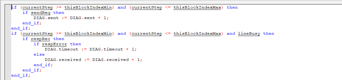
Figure 13 - ManageDiagnostics section
Please note that „sendReq”, “respRec” and “respError” are set to 1 only for one cycle in next sections.
5.6.3 ManageRequest
This is to save current request along with Modbus Slave address in “request” structure so it can be used by DATA_EXCH block in EXCHANGE_OVER_SERIAL_LINE function block at the end of NOM0200_SLOT6_PORT0 section.
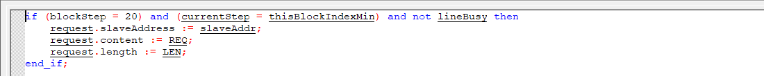
Figure 14 - ManageRequest section
5.6.4 ManageResponse
This is to determine communication failure and save data upon proper response. Value of “respRec” comes from EXCHANGE_OVER_SERIAL_LINE function block and basically mean that communication block completed data exchange. It may be confusing because it shouldn’t be set on timeout, but it is. The problem with NOM0200 module is that even if the Slave doesn’t exist in the network, NOM0200 module return a value like if it would be there. The response is exception code 0x06. This is not normal, but it was discussed in Modicon PLCs -> Ethernet Communication -> Alternatives -> Summary. Value of “respError” comes from EXCHANGE_OVER_SERIAL_LINE function block as well. It is where we suppose to get our timeout but somehow, we don’t. And it is also not normal. It looks like a firmware issue or I don’t know how to set communication parameters properly. Eventually, it was impossible for me to detect timeout but only exception code 0x06 and this is the reason why this code is as it is. Definitely, there is a room for improvement if You are planning to build Modbus Master on other type of controller.
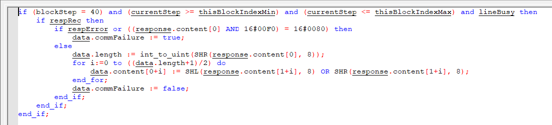
Figure 15 - ManageResponse section
5.6.5 ManageStep
We have already distinguished “currentStep” that is used across all the program for specific COM PORT and “blockStep” which is used for each POLLING_SCHEDULE function block. My intention was not to block the code if specific POLLING_SCHEDULE block is not ready to be executed, meaning activation condition is not met.
Here, we can see that “blockStep” is initially set to 10 and it is waiting for the activation but at the same time, when the line is free it doesn’t stop “currentStep” to go on to other blocks that might be activated already. Block activation makes “blockStep” go to 20 where it waits for the line to be released and free to use. Second IF condition is for request repetition if case of error. Once the line is ready, this block takes a line by setting “lineBusy” bit by which other blocks will know that the line is taken. Once the line is taken, “sendReq” is activated as well and “blockStep” is set to 30. Details of request are managed by previously mentioned ManageRequest section. PLC goes though all the program reaching EXCHANGE_OVER_SERIAL_LINE function block where “sendReq” activates DATA_EXCH block initiating communication. On next PLC cycle, “sendReq” is being reset and “blockStep” is set to 40. Keep in mind that for the clarity of the program, I want to manage “sendReq” in one place. I intentionally reset it here, not after or inside EXCHANGE_OVER_SERIAL_LINE function block. In “blockStep” 40, we are waiting for response. Response is managed in ManageResposne section, here we just manage “currentStep”. On error, request is retired (if retires is more that 0). On correct response, “currentStep” is set for the next POLLING_SCHEDULE block, the line is released and “blockStep” goes back to 10 to wait for the next activation.
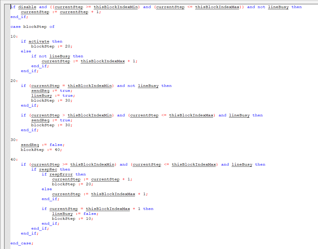
Figure 16 - ManageStep section
5.7 VACON_VSD_DATA_ASSIGN function block
In Vacon VSD, there are not many parameters that I might be interesting in and all I need is basically in one place in the memory. But other devices may have required data spread all over wide range of addresses so You would have multiple frames and would have data that You don’t need. Not only for that reason but also to keep Your code clean You should consider aggregating all data in one place. In my case, I have created custom data type to hold all required data. VACON_VSD_ASSIGN_DATA function block is used to collect them.
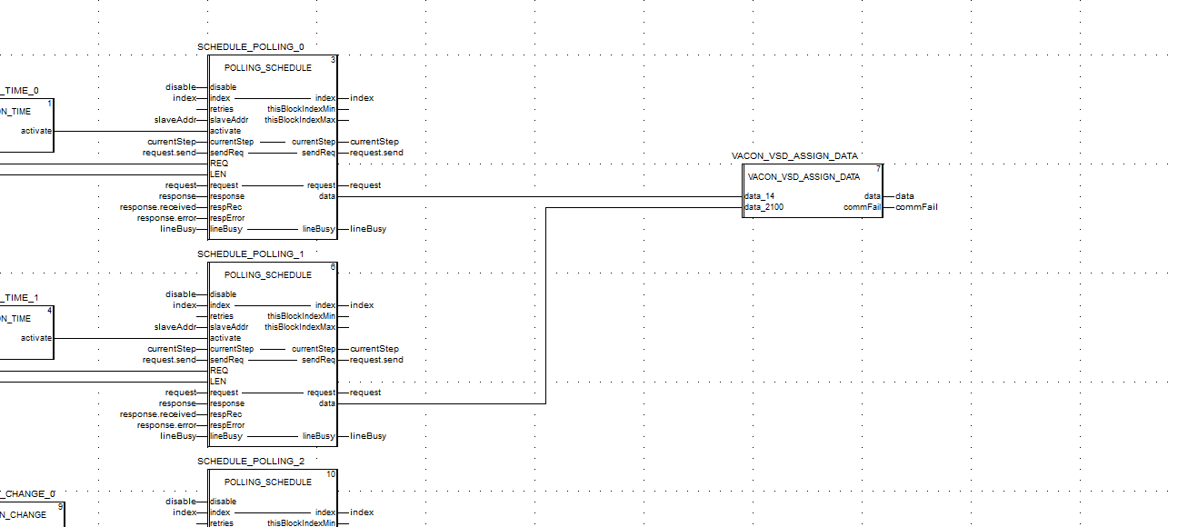
Figure 17 - VACON_VSD_DATA_ASSIGN function block
Output data type consist of all variables in understandable way.
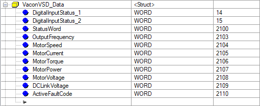
Figure 18 - VaconVsd_Data structure
For devices with bigger number of variables, You need to be careful not to make a mistake in assignment because You refer to data with an array index.
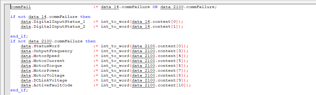
Figure 19 - VACON_VSD_DATA_ASSIGN function block logic
Additionally, communication failure bit is created here.
5.8 VACON_VSD_SOURCE_SELECT function block
Simple section that uses input/output type. Activating “simulate” bit stops assigning data from POLLING_SCHEDULE block and allows to change variables manually. Pretty useful for testing.
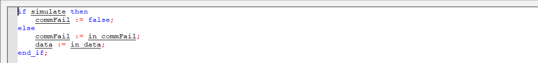
Figure 20 - VACON_VSD_SOURCE_SELECT function block
5.9 NOM0200_SLOT6_PORT0 variable
This variable is a custom type.
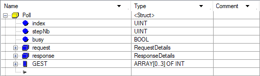
Figure 21 - Poll structure
One structure holding all data required for COM PORT operation. With such data type, it is easy to build another sections of PLC managing other COM PORTs.
5.10 Other data types
Those data type was created to keep the code clean and convenient to use.
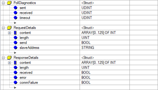
Figure 22 - Other structures
6. Concerns
NOM0200 has its own firmware, and it is communicating with CPU over the backplane. You cannot think about the program as of direct serial port access point.
One of the problems I faced is related to number of reties. For Modicon M580 controller I was forced not to manage number of reties by the code and use NOM configuration instead. I observed that with a time, my requests were delayed more and more. Like if there was some kind of buffer within NOM card. After some time of working, what I saw on serial port and on the code went out of sync. The other question rise here. What is the size of that buffer and what happens when it is full. Eventually, for live system, I had to change number of reties to 1, answer delay to 1000ms and delay between frames to 10ms. My baud rate was 19200.
The idea ratio of read frames is 3:1. The faster PLC cycle is, the faster data exchange between Master and Slave is, the closer to ideal ratio 3:1 we can get. But as every process takes time, we will never get exactly 3:1 ratio.
Would it be better to use a buffer for frames? You can that method. The question is how big it should be, how You would fill the buffer and what mechanisms You would implement not to overflow it. How would You feed command to it?
Command priority is another concern to think of. FC5,6,15,16 can be activated any time and in the worst case, if the timing is unfavorable, command may go as the last one in order. There is a room for improvement to make a mechanism prioritizing commands.
Communication failure needs deeper discussion as well. How restrictive my system should be? Should I set communication failure if at least one frame returns an error? What if I poll for date and time every minute? One error frame would set communication failure for a minute where other frames are refreshed correctly in seconds. Maybe, there should be some kind of adoptive mechanism implemented? Let’s say communication failure is set when two of three frames in a row return and error. There are a lot of different approaches, and this is defiantly something that You need to adopt to Your specific configuration.
7. Summary
Although it seems easy when You think about Modbus Master functionality, implementing it may be challenging. Different concerns may rise depending on the approach and way implementation itself. Even in this example there are plenty of room for improvement.
Feel free to utilize this example for Your needs.
Source code here.