1. Objective
The idea of this project is to control exterior venetian blind consisting of multiple slats that can be adjusted to control light and privacy. Blind controller should allow short button press to make micro adjustments of slat angle as well as long button press to fully open and close the blind – drive to both up and down position. Moreover, there should be a way for external commands:
- remote control with smartphone,
- remote control from some kind of weather station to protect blinds against strong wind.
Although external commands are not a part of this article, I had to take them into account from the beginning. As this project started at the early stage of house construction, there was to decide where to place blind controllers. Whatever to put them in the junction box near the blind along with the button or inside dedicated control panel. Both solutions have pros and cons but eventually it was decided to place them in dedicated panel. The movement of the blind up/down and slats rotation are performed using internal mechanism in the 230VAC actuator (a bi-directional motor). Wall mounted momentary buttons will be used. The controller should fit in DIN rail mounted one module wide enclosure. Total amount of windows blind is 15.
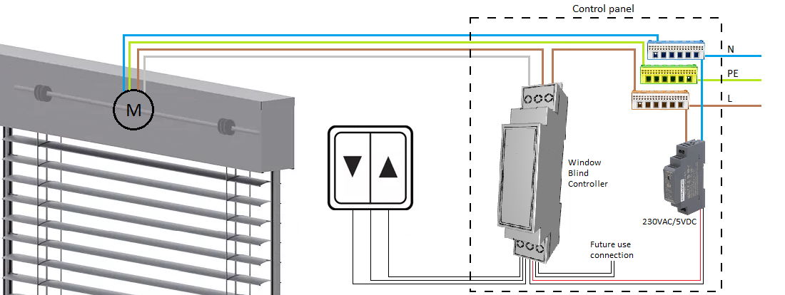
Picture 1 - Visualization of project concept
2. Solution selection
Low power consumption microcontroller Attiny84 has been selected. Supplied with 5V, in active mode (1MHz clock, 25dgrC), it consumes less than 1mA. Most of the time window blind will stay at the same position and windows blind controller will wait for the user to press the button. We can safely assume current consumption of 1mA an average. That gives less than 9Wh annually. Multiplied by 15 window blinds in the house, gives 135Wh annually.
Project requires operating 230VAC load. Several ideas were considered:
- Solid state relay (rejected due to price and size of relays),
- Electromechanical relay,
- Triac + optotriac.
Although triacs are not that straightforward to use as relays, they have been selected because:
- they do not have mechanical component which means they can last longer,
- they are smaller and easier to fit on PCB when space is limited,
- they are cheaper even if require additional components.
Whatever triacs or relays, they need to be properly rated to operate inductive load. In general, I trust more triacs than relays. I have changed a lot of damaged relays in my career. I changed triac only one time when user plugged 24V rated component to 230VAC system by mistake. As in this project, I had to go with one module wide, DIN rail mounted enclosure, I would have to find proper miniature, PCB mounted relays for inductive loads. From my research, they are inadequately expensive to the needs of this project.
Both triac and relays consume energy when they are active. I don’t like the idea of an output being activated when not needed. In case of window blind, this is going to happen when the blind reaches its limit position. I want to deactivate an output after the movement stopped. I do not have access, and I am not allowed to interfere with the internal structure of an actuator. The only way I can detect whatever motor stopped on limit position is to monitor the current flow. Limit switch cuts off 230VAC supply to the motor so no current means windows blind reached its limit position and controller output can be deactivated. For that purpose, I installed diodes and no matter what’s the current consumption of an actuator, I always get 2.1VAC across them. With proper resistor, 2.1VAC is enough to activate SFH6206 optocoupler and change signal on microcontroller input.
At the design stage, I didn’t know what type of actuator will be used and I wanted the window blind controller to have some margin of use. 1N4007 diode rated for 1A seemed too small so from the beginning, I tried to rate it for current up to 3A. This is the reason I used 1N5408 diode.
Triac selection was tricky for me, and I spent a lot of time before I found proper solution. I had already done several other projects on triacs but never for inductive loads. I normally used BT136, but it burned every time I tried to change rotation direction. Eventually I came across so called snubberless triacs. I applied the same current rating strategy here as for diodes. I wanted the triac to be rated for at least 3A. Due to availability of components and the prices, I ended up with oversized BTA16-800CW triac rated for 16A.
Optotriac MOC3043 allows safe connection of 230VAC load to 5V microcontroller. Selected resistor of 620 ohm value makes it consume ~6mA when active.
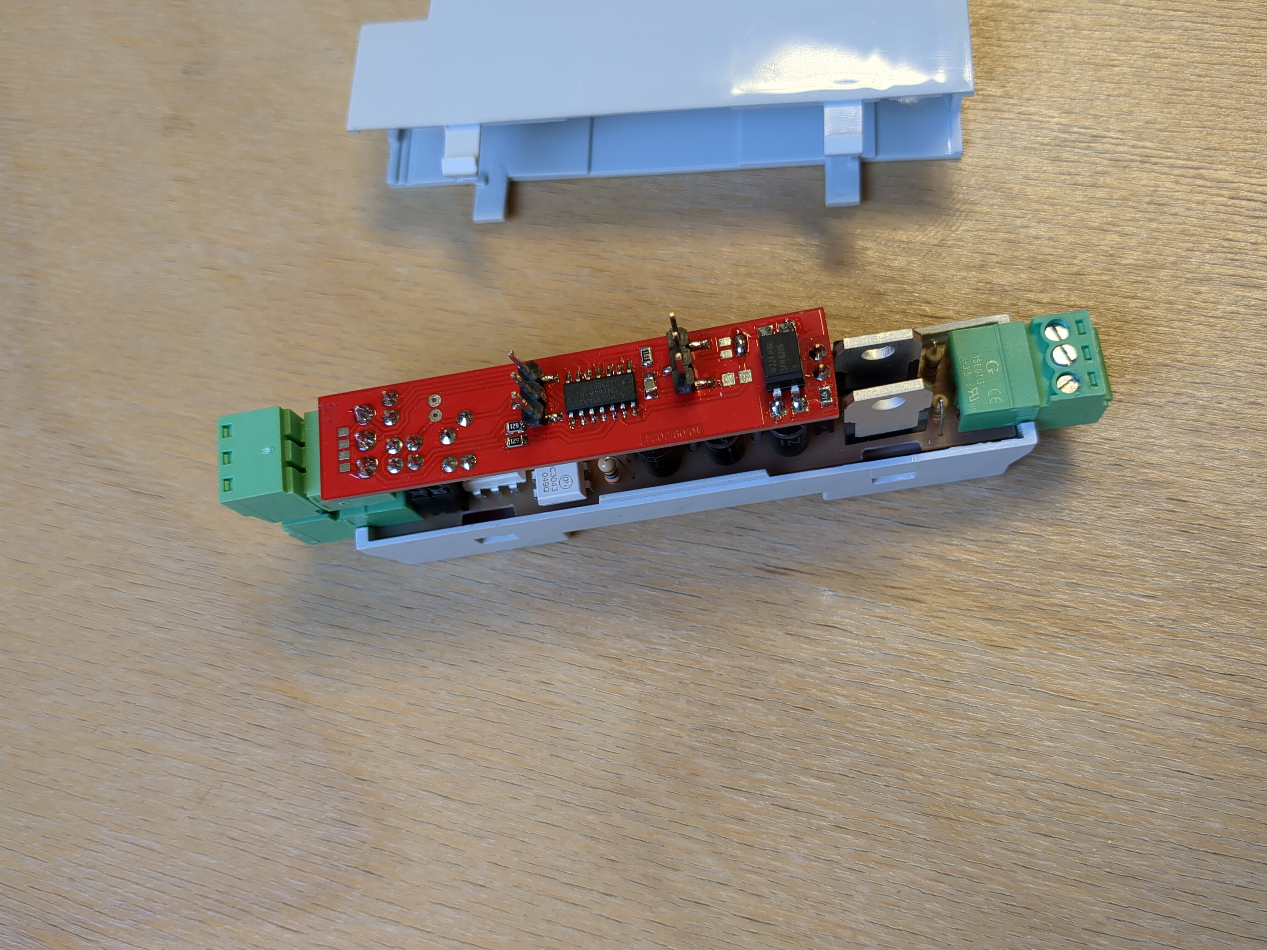
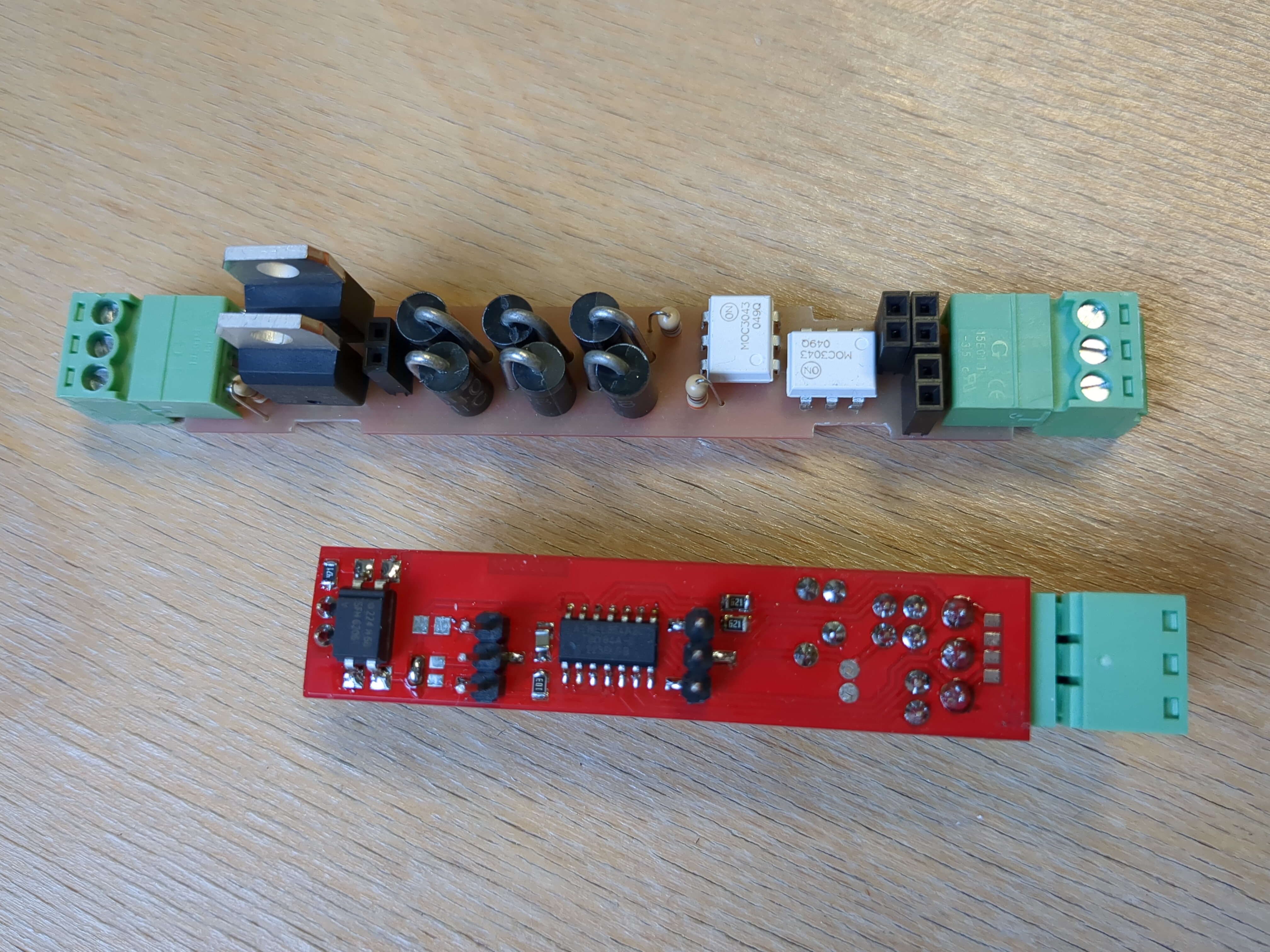
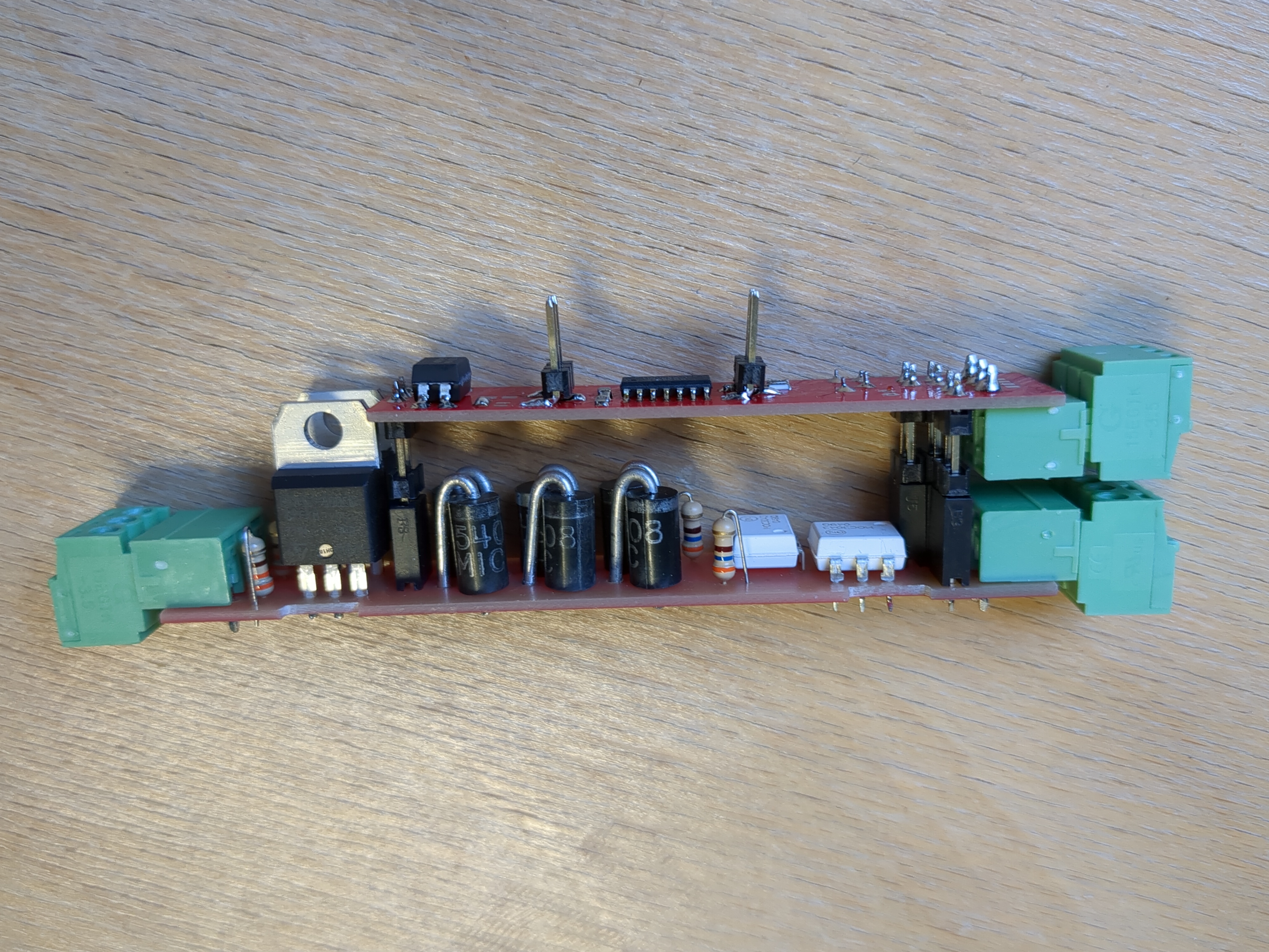
Due to the size of enclosure and space availability, there are two PCBs. I tried to separate 230VAC (executive board) from 5VDC (controller board). As the circuit is relatively simple, I decided to go with one layer PCB. Red dashed line of the schematic visually separates 230VAC from 5VDC. Black dashed border lines segregates components within each board – controller (top) board and executive (bottom) board. Boards are connected using H4 and H6 terminals. H1, H2, H3 are external connections. For future external command signals pin 1 and 3 of H3 connector were selected. H5 is programmer connection.

Picture 2 - Window Blind Controller schematic
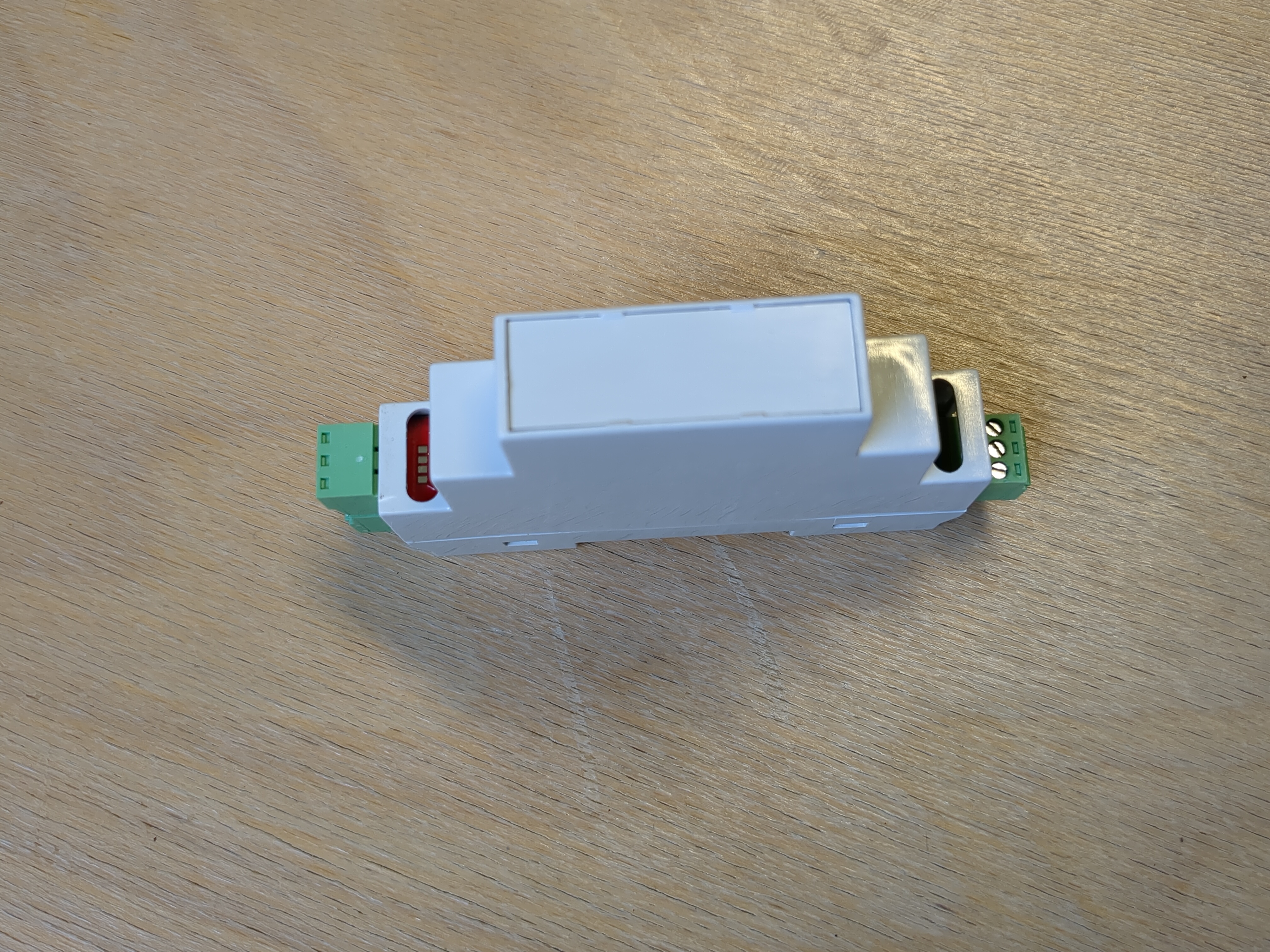
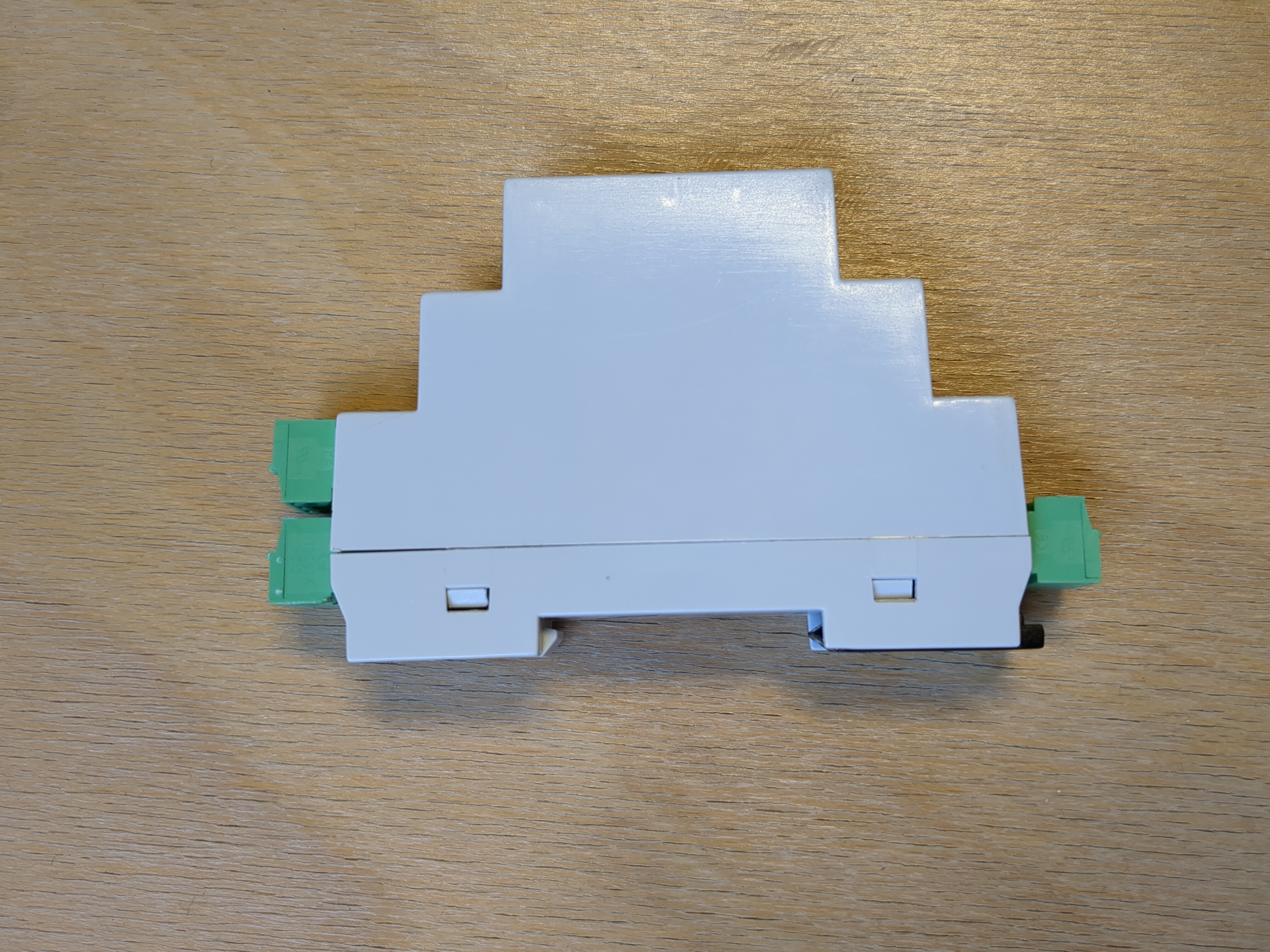
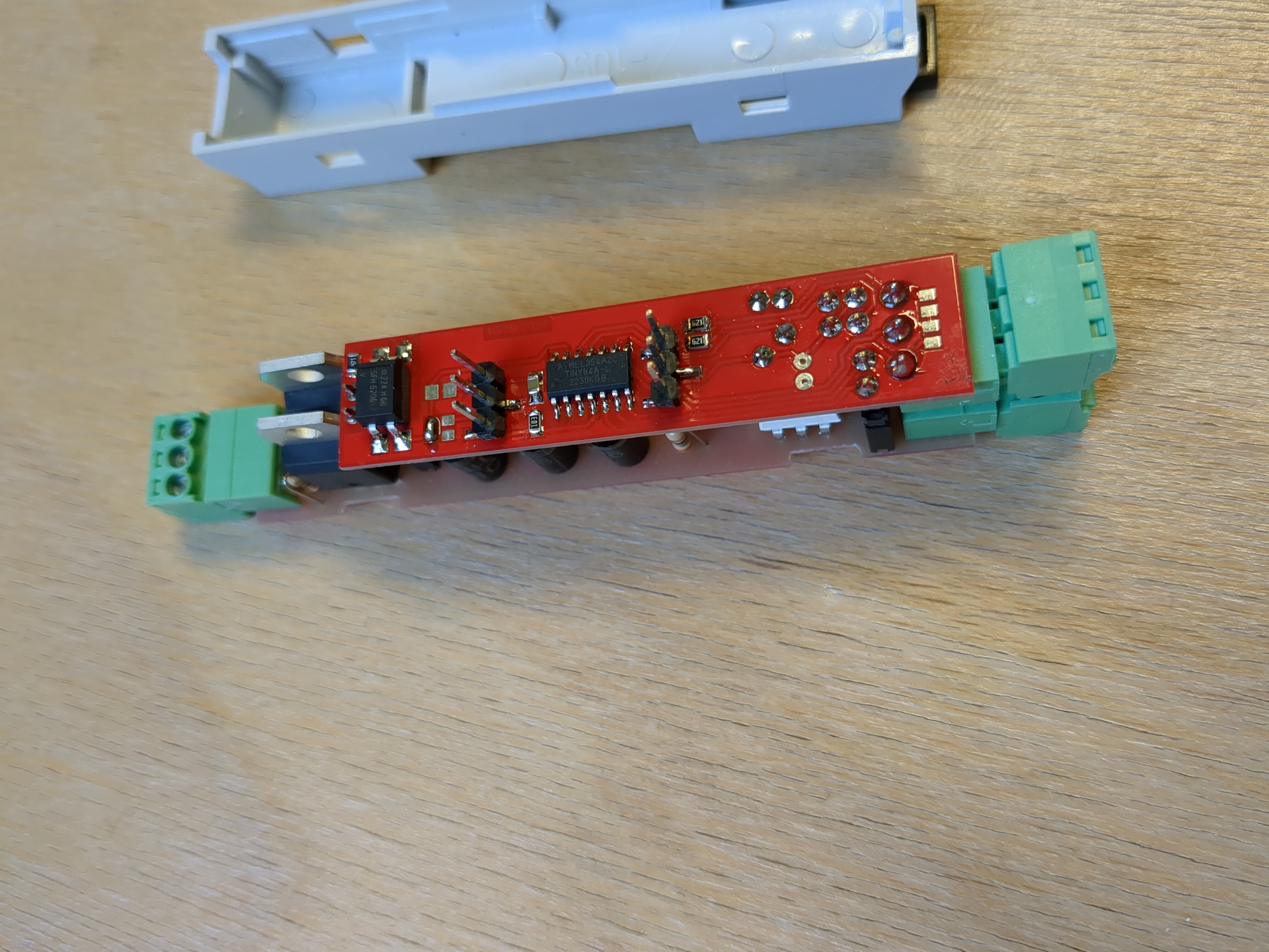
3. Device presentation
4. Code
Software tag names will be the same as GPIOs shown on the schematic:
- BUTTON_UP
- BUTTON_DOWN
- LIMIT_SWITCH
- ROTATE_UP
- ROTATE_DOWN
I need a simple and clear way of detecting changes of signals. I need to:
- detect change from 0 to 1 – raising edge of signal,
- detect change from 1 to 0 – falling edge of signal,
- apply delay for the signal – intentional delay required by hardware, input flickering filtration, duration of button press time detection.
4.1 SIGNAL_DELAY
For the purpose described above, I created library named SIGNAL_DELAY. SIGNAL_DELAY class constructor takes two parameters which are “activationTimeDelay” and ”deactivationTimeDelay” and it works as shown on below diagram.

Picture 3 - SIGNAL_DELAY
Rising and falling edges are represented here as signal spikes. In fact, they are impulses of one controller cycle time. Program runs in infinite loop constantly monitoring (scanning) inputs. When a change is detected, the information about it is available until next loop step (next input scan).
Library is written in C++ and then used in Arduino IDE.
Here is SIGNAL_DELAY.h header file.
          #ifndef SIGNAL_DELAY_h
          #define SIGNAL_DELAY_h
          #include "Arduino.h"

          class SIGNAL_DELAY {
              private:
                  bool inputStatePrev;
                  bool active, activePrev;
                  bool risingEdge, fallingEdge;
                  unsigned long activationDelay;
                  unsigned long deactivationDelay;
                  unsigned long inputChangeStartingTime;
                  void signalDelay(bool inputState);
                  void edgeDetection(void);

              public:
                  SIGNAL_DELAY(unsigned long activationTimeDelay, unsigned long deactivationTimeDelay);
                  void scan(bool inputState);
                  bool isActive();
                  bool isRisingEdge();
                  bool isFallingEdge();
          };

          #endif
Here is SIGNAL_DELAY.cpp file with the class implentation.
          #include" Arduino.h"
          #include" SIGNAL_DELAY.h"

          SIGNAL_DELAY::SIGNAL_DELAY(unsigned long activationTimeDelay, unsigned long deactivationTimeDelay) {
              activationDelay = activationTimeDelay;
              deactivationDelay = deactivationTimeDelay;
          }

          void SIGNAL_DELAY::scan(bool inputState) {
              signalDelay(inputState);
              edgeDetection();
          }

          void SIGNAL_DELAY::edgeDetection(void) {
              if (!activePrev && active) {
                  risingEdge = true;
              }
              if (activePrev && active) {
                  risingEdge = false;
              }
              if (activePrev && !active) {
                  fallingEdge = true;
              }
              if (!activePrev && !active) {
                  fallingEdge = false;
              }
              activePrev = active;
          }

          void SIGNAL_DELAY::signalDelay(bool inputState) {
              if (inputStatePrev && inputState) { // high
                  if ((millis() - inputChangeStartingTime) >= activationDelay) {
                      active = true;
                  }
              }
              if (!inputStatePrev && inputState) { // rising edge
                  inputChangeStartingTime = millis();
              }
              if (!inputStatePrev && !inputState) { // low
                  if ((millis() - inputChangeStartingTime) >= deactivationDelay) {
                      active = false;
                  }
              }
              if (inputStatePrev && !inputState) { // falling edge
                  inputChangeStartingTime = millis();
              }
              inputStatePrev = inputState;
          }

          bool SIGNAL_DELAY::isActive() {
              return active;
          }

          bool SIGNAL_DELAY::isRisingEdge() {
              return risingEdge;
          }

          bool SIGNAL_DELAY::isFallingEdge() {
              return fallingEdge;
          }
4.2 Attiny84
I am using USBasp programmer. First thing to be done is to set fuse bits. I read them with:
avrdude -c usbasp -p t84 -B 10 -U lfuse:r:-:i -U hfuse:r:-:i -U efuse:r:-:i
With:
avrdude -c usbasp -p t84 -B 10 -U lfuse:w:0x62:m -U hfuse:w:0xDF:m -U efuse:w:0xFF:m
I set my microcontroller to use internal clock of 1MHz. I indicated processor speed at the beginning of my program.
I want to protect my device against unexpected microcontroller failures so I implemented 2s watchdog. If watchdog is not reset within 2s, microcontroller restarts.
Then I initialize my GPIO and manage them.
          #include <avr/wdt.h>

          void setup() {
              wdt_reset();
              wdt_enable(WDTO_2S);
              initIO();
          }

          void loop() {
              manageIO();
              wdt_reset();
          }
For the clarity of the program, GPIO functionality was moved to a separate file.
First, I define constants for pin selected for specific signal. It reflects hardware connection shown on the schematic. Second, I define rotation bits which I am going to use to set outputs. Third, I define SIGNAL_DELAY variables. Variables buttonUp and buttonDown with 50ms on and off delay for input flickering filtration. Variables buttonUpLongPress and buttonDownLongPress to specify how long the button should be held to latch the output so the blind can drive to its limit position without person standing next to it. I my case the time is set to 2s. Variables rotateUp and rotateDown with off delay of 1s. As I am going to operate inductive load, I can’t switch directions immediately. I need to wait for a short moment to change rotation direction. Variable limitSwitch with on delay of 10ms – because signal is correlated with 230VAC 50Hz sin wave.
In initIO() function, I initialize inputs and outputs. For all inputs, I activate internal pullup resistor so they all are normally high.
          #include <SIGNAL_DELAY.h>
          #define ROTATE_UP 1
          #define ROTATE_DOWN 2
          #define BUTTON_UP 7
          #define BUTTON_DOWN 8
          #define LIMIT_SWITCH 0

          bool rotateUpCommand;
          bool rotationUp_Latched;
          bool rotateDownCommand;
          bool rotationDown_Latched;

          SIGNAL_DELAY buttonUp(50, 50);
          SIGNAL_DELAY buttonDown(50, 50);
          SIGNAL_DELAY buttonUpLongPress(2000, 0);
          SIGNAL_DELAY buttonDownLongPress(2000, 0);
          SIGNAL_DELAY rotateUp(0, 1000);
          SIGNAL_DELAY rotateDown(0, 1000);
          SIGNAL_DELAY limitSwitchActivated(10, 0);

          void initIO() {
              pinMode(BUTTON_UP, INPUT_PULLUP);
              pinMode(BUTTON_DOWN, INPUT_PULLUP);
              pinMode(ROTATE_UP, OUTPUT);
              pinMode(ROTATE_DOWN, OUTPUT);
              pinMode(LIMIT_SWITCH, INPUT_PULLUP);
          }

          void manageIO() {
              buttonUp.scan(!digitalRead(BUTTON_UP));
              buttonDown.scan(!digitalRead(BUTTON_DOWN));
              buttonUpLongPress.scan(buttonUp.isActive());
              buttonDownLongPress.scan(buttonDown.isActive());
              limitSwitchActivated.scan(digitalRead(LIMIT_SWITCH));
              rotateUp.scan(rotateUpCommand);
              rotateDown.scan(rotateDownCommand);

              if (buttonUpLongPress.isRisingEdge()) {
                  rotationUp_Latched = true;
              }
              if (buttonDownLongPress.isRisingEdge()) {
                  rotationDown_Latched = true;
              }
              if (!rotationUp_Latched && !rotateDown.isActive() && buttonUp.isRisingEdge()) {
                  rotateUpCommand = true;
              }
              if (!rotationUp_Latched && buttonUp.isFallingEdge()) {
                  rotateUpCommand = false;
              }
              if (rotationUp_Latched && (buttonUp.isRisingEdge() || buttonDown.isRisingEdge())) {
                  rotateUpCommand = false;
                  rotationUp_Latched = false;
              }
              if (!rotationDown_Latched && !rotateUp.isActive() && buttonDown.isRisingEdge()) {
                  rotateDownCommand = true;
              }
              if (!rotationDown_Latched && buttonDown.isFallingEdge()) {
                  rotateDownCommand = false;
              }
              if (rotationDown_Latched && (buttonDown.isRisingEdge() || buttonUp.isRisingEdge())) {
                  rotateDownCommand = false;
                  rotationDown_Latched = false;
              }
              if ((buttonUp.isActive() && buttonDown.isActive()) || limitSwitchActivated.isRisingEdge()) {
                  rotateUpCommand = false;
                  rotationUp_Latched = false;
                  rotateDownCommand = false;
                  rotationDown_Latched = false;
              }

              digitalWrite(ROTATE_UP, rotateUpCommand);
              digitalWrite(ROTATE_DOWN, rotateDownCommand);
          }
In manageIO() function, I constantly scan every signal for a change. When BUTTON_UP is pressed, ROTATE_UP output is activated immediately. When BUTTON_UP is released ROTATE_UP output is deactivated immediately. It is true until long press is detected. When long press is detected, output stays active until either LIMIT_SWITCH is reached or any button is pressed. The same logic applies to BUTTON_DOWN input and ROTATE_DOWN output. On the top of that, I need to avoid both outputs being activated simultaneously so pressing both BUTTON_UP and BUTTON_DOWN switches, deactivates outputs.
5. Cost
I purchased components to assemble 16 devices so I got better price per component. The cost of all components used per one device is ~11.50 USD (for 2023/2024). The price includes PCB manufacturing and shipments.
There is still a lot that I can't put a price on:
- components and time used for the prototype (including mistakes and failures during that process),
- PCB design time,
- soldering materials, energy and time used,
- programming time,
- microcontroller programmer (I had none before I started this project),
- materials to place (a panel), connect (wiring and cables) and supply (230VAC/5VDC power supply) the deivce for the final use,
- deploying and commissioning time.
It is also worth mentioning that people who do such projects usually have some electronics components left from other designes. For instance, I didn't need to buy 10k resistors or 100nF capacitors as they came in hundreds when I first time bought them.