People tend to simplify their work and reduce effort. Automation engineers tend to use short variable names, sometimes too short. Usually there is no problem for analog variables. We subconsciously choose the correct names like pressure, temperature, etc. But when it comes to Boolean variables, which mainly this article is about, for some reason, it is not so obvious what variable name to choose. If variable name is not carrying correct information, the code becomes unreadable. It’s hard to read, hard to troubleshoot. Don’t be afraid to use longer variable names to show what You really mean.
I have seen plenty of meaningless variables. One of the most commonly used in automation is “status”. What did author mean by it? Good question! We are lucky when such variable comes with description like the following “1 – local position, 0 – remote position” but it is not always the case. In fact, status can be anything. Open/close status, auto/manual status, local/remote status, trip/normal status and so on.
Variable name should describe the value it holds in unambiguous way. In case of Boolean variable, value should confirm the variable. Let me give few examples to clarify what I mean:
- if variable named “LightIsOn” is active (logical “1”), it means that the light is on,
- if variable named “LightIsOff” is active (logical “1”), it means that the light is off,
- if variable named “lowTemperature” is active (logical “1”), it means that the temperature dropped to the level considered low,
- if variable named “thisIsEasyToUnderstand” is active (logical “1”), it means that what I am trying to explain here is easy to understand.
So, when a wiring diagram shows that there is a key that allows remote control (turning the key ON activates digital input – logical “1”) it means that variable should be named “Remote”. When a wiring diagram shows that relay contact is closed and activates both digital input and closes the control circuit, it means that variable should be named “Close”.
Let’s look at below code example:

Any concerns? Variable name “Motor” is often used in tutorials that sometimes forget to mention that “Motor” is just one of hundreds of motors in the facility. Even if Your system is simple and really contains one motor, You should not create variable named “Motor”. Every component in the system has its tag. If You are not electrical staff and all You need is to start and stop the motor, You can create variable name based on motor tag. If You are managing big system with hundreds of thousands of variables, maybe You will need to develop some kind of strategy for tags management. In this case Your variable name may not be based on motor tag but on location, purpose or any other categorization method. In my case, where I manage Electrical Control System, the most effective way is to create variable names based on substation, MCC and cubicle that they are supplied from. Let’s rename variables so they are more specific.

Better but I still have one concern about it. Variable “Common” is not clear to me. Common what? Common status? Common condition? Common trip? I know what the author meant by that because I am the author. How about You? I want to have one general signal that I want to pass to upstream system (SCADA) to notify them that there is a problem with the motor. They won’t know what’s the problem exactly, but they will know it appeared and ask responsible personnel to resolve the issue. SCADA operators don’t need to have electrical knowledge. They need to know how to control their process. Electrical personnel are responsible for electrical issues. And You, automation engineer, are an interface between them. Let’s rename “Common” to something clearer.

By above code I am referring to the motor supplied by Substation 08, MCC1234, cubicle AF01 and I intend CommonFailure to be activated when motor trips or when in alarm while running. I don’t want to set any flags when the motor is not running. In other words, SCADA operators doesn’t care about alarm when motor is stopped.
Let’s see how the code looks on the PLC. PLC IDEs allow online code animation.

If You are familiar with basics of ECS, You will see that something’s wrong. When motor is tripped, the contactor should be opened but our code shows it is close. The problem here is that the Trip signal is so called "fails safe signal". Which means it is on in normal conditions, and it is off when something happens. If we follow mentioned strategy that value confirms the variable, name of this variable should be “NoTrip” or “Normal” or “Enabled”. It is not the best choice for variable name in this case. You need to know that almost every system has its own local HMI. Yes, You can display on HMI that trip condition is met and motor can be started but when something happens, alarm needs to be raise. There is a special alarm view to keep all alarms (trips) along with date and time. It doesn’t make sense to display in alarm list that motor is “NoTripped” or it is “Normal”. What You need to display is “Alarm” or “Trip”. What to do in this case? Invert the signal.

Now, whatever You are looking at above code animated or not, it is clear what’s its purpose.
Whenever inversion is required, consider inverting signal at the source. Let me give another example. Let’s say that I need to update data based on communication status. If communication is healthy, I save received data. If not, I hold previous data unchanged. What variable name do I choose for communication status and why?

I was asked once, why do I always use “NOT CommFail” in my “IF” conditions. It would be easier to read the code if my variable name is “CommOK” instead. There are two reasons I don’t recommend “CommOK”. Communication failure is definitely something that I want to display on HMI in my alarm list and as mentioned above, I don’t want to put CommOK in there. Second reason is that I want to be consistent with variable names that I use across whole system. I could use “CommOK” on the PLC and “CommFail” on HMI with inversion on HMI. But in this case, I have two different names one on PLC another on HMI. I prefer to stick to one variable and use it everywhere.
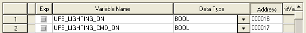
Now let jump to another example. Let’s say You see such variable in Your variable list.

Is it status or command? Does this variable tell that lighting is on when the value is 1? Or is it a command that needs to be set to switch on the lighting? If You dig in the code, You are going to find out. But why? Why not to determine it from variable name? As in my systems there are much less commands than statues, whenever I need to create command variable, I explicitly show it. If there is no “cmd” in the variable name, I consider it as status. For example:
Again, You should have some kind of strategy for variable naming. Variable name selection is often overlooked in small systems. Let’s consider that Your company is building environmental metering stations to monitor basic air conditions. You will end up with multiple systems (multiple PLCs) which are exactly the same. That’s great, You can write the program (code) once and download it to every PLC. But how would You gather all data from all metering stations? If the protocol is address based (like Modbus) it will not be a problem. But if the protocol is variable name based (like OPC), You would have a problem because You have the same variable names in different systems. This is another aspect of variable name selection to think about. Your variable names might need to be unique across all Your PLCs which forces You to work more but allows You to gather information easily.
Selection of variable name is not the only thing that helps making the code readable. In text-based programming, code formatting is as much important. If You don’t use indentation properly, the code will be unreadable. Some IDEs do it for You. If not, You need to take care about this matter Yourself.
Another aspect I would like to mention is selection of IEC61131-3 language. As You are aware, there are five standard languages used in automation:
- Ladder Diagram (LD)
- Instruction List (IL)
- Function Block Diagram (FBD)
- Structured Text (ST)
- Sequential Function Chart (SFC)
I have used LD, ST and FBD frequently. I came across few programs in SFC but I have never seen any PLC programmed with IL and I have never used Instruction List myself.
I have met many automation engineers asserting the superiority of one language over another. But reality is not that easy. Every major company developed their own IDE. Rockwell Automation RSLogix used to come, by default, only with Laddar Diagram. Schneider Electric Control Expert (Unity Pro) offered all languages, but Ladder Diagram was horrible to me. I had similar problem with CodeSys FBD. I am trying to talk about them in past tense as they might have changed, and I am not aware of it. What’s more, some low-cost PLCs are programmed in “C” like language (I am not even sure if they follow IEC61131-3 standard). What I am trying to say is that sometimes we have no choice. If we do, we tend to select the language we are used to the most. But if fact, programming language should be selected based on system type and code section functionality.
In my work, I try to select language for specific code section. Before I start coding, I try to judge what language would be best for writing, reading and troubleshooting. For example:
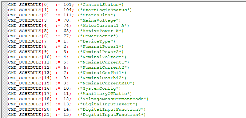
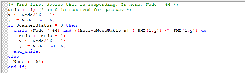
-
If I need to initiate elements of the table in the code, I will choose ST. It is easy to write, even generate the code externally and paste it as simple text. If variables are aligned in a proper way, it is easy to read. It is compact (doesn’t take too much space at the section)
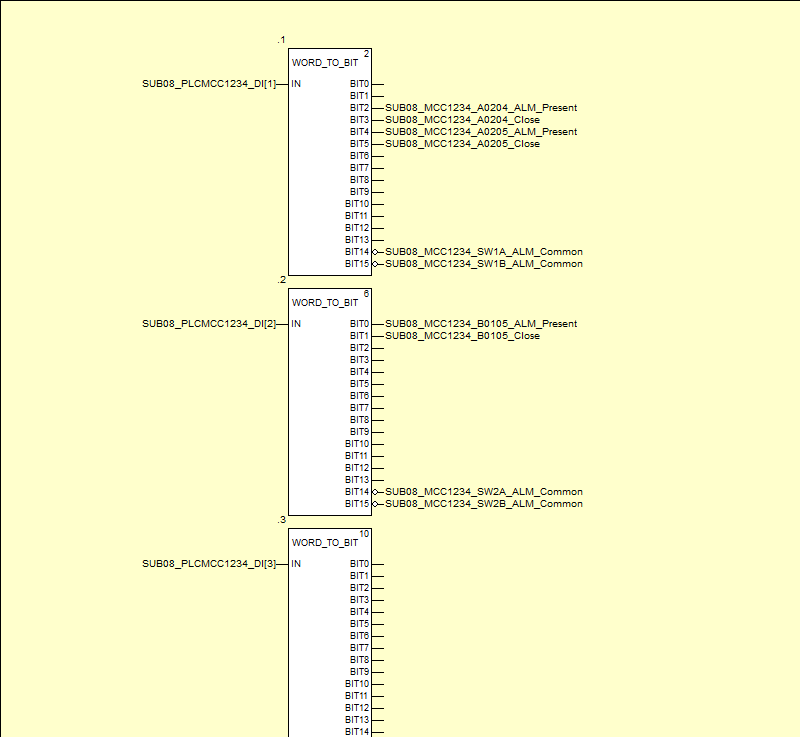
-
If I need to unpack bits from words which are holding digital inputs, I will use FBD. FBD will take more space within the section, and it is more problematic to write (lots of mouse clicks and manual variable selections) but it is very easy for troubleshooting. I can immediately match which word reflects which physical input module. I can see which inputs has been inverted and which are spare (the one not assigned).
-
If I need to make som calculations or bit operation within the word, I will choose ST because it is easy to write. In this case, I will most likely end up with custom function block.
-
If a function block consists of multiple inputs and outputs, I will most likely choose FBD for easy visualization what are my inputs and what are my outputs.

-
Here is an example of Ladder Diagram usage. Although I usually avoid LD, below section of the code clearly shows what conditions need to be met to start the motor.
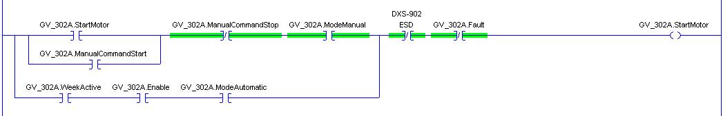
It is possible to represent each of above example in different programming languages (maybe except while loop that is usually unavailable in LD and FBD)? Of course! But will the code become easier to read, to write? Not necessarily.
The last aspect I would like to talk about is instructions like: “Label”, “GoTo”, “Jump” etc. They are used to make jump in the program. Some IDEs allow those functions, but I strongly recommend not to use them. You can easily lose track of what Your program does. Keep in mind that there is always a way to replace them with correctly constructed condition “if” or a loop. The same rule applies to pointers. Siemens allowed using pointer in their IDE. Although this is very powerful tool, it might be extremely hard to troubleshoot. If You want to use pointer, You really need to understand what You do.
Summarizing:
- have a strategy for variables naming
- use clear, unambiguous, unique variable names
- explicitly differentiate between signals and commands
- make inversion at the source
- use “fault”, “failure”, “alarm”, “trip” instead of “normal”, “good”, “healthy”
- choose programming language carefully
- use code formatting for text-based languages
- avoid jump instructions
- avoid pointers
I also encourage You to read Clean Code by Robert C. Martin.