1. Context
You are working in the environment where a measurement of specified PV is required. You need to ensure uninterrupted process and can't afford to stop production process when Your measuring device fails or when replacement of measuring device is needed. In such circumstances, You can't rely on a single transmitter. You have decided to use triple redundancy. You are going to install three identical transmitters and take action based on readings from all three of them.
2. Specification
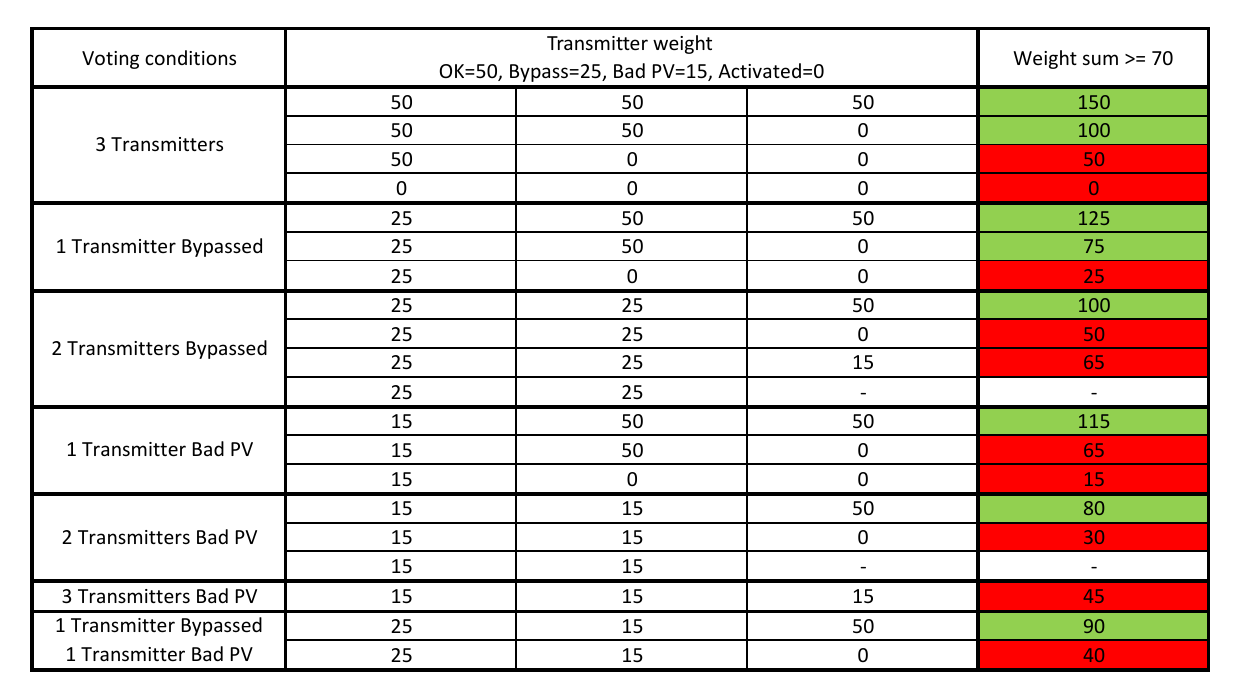
2 out of 3 (2oo3) logic is meant to be used as per the following specification,
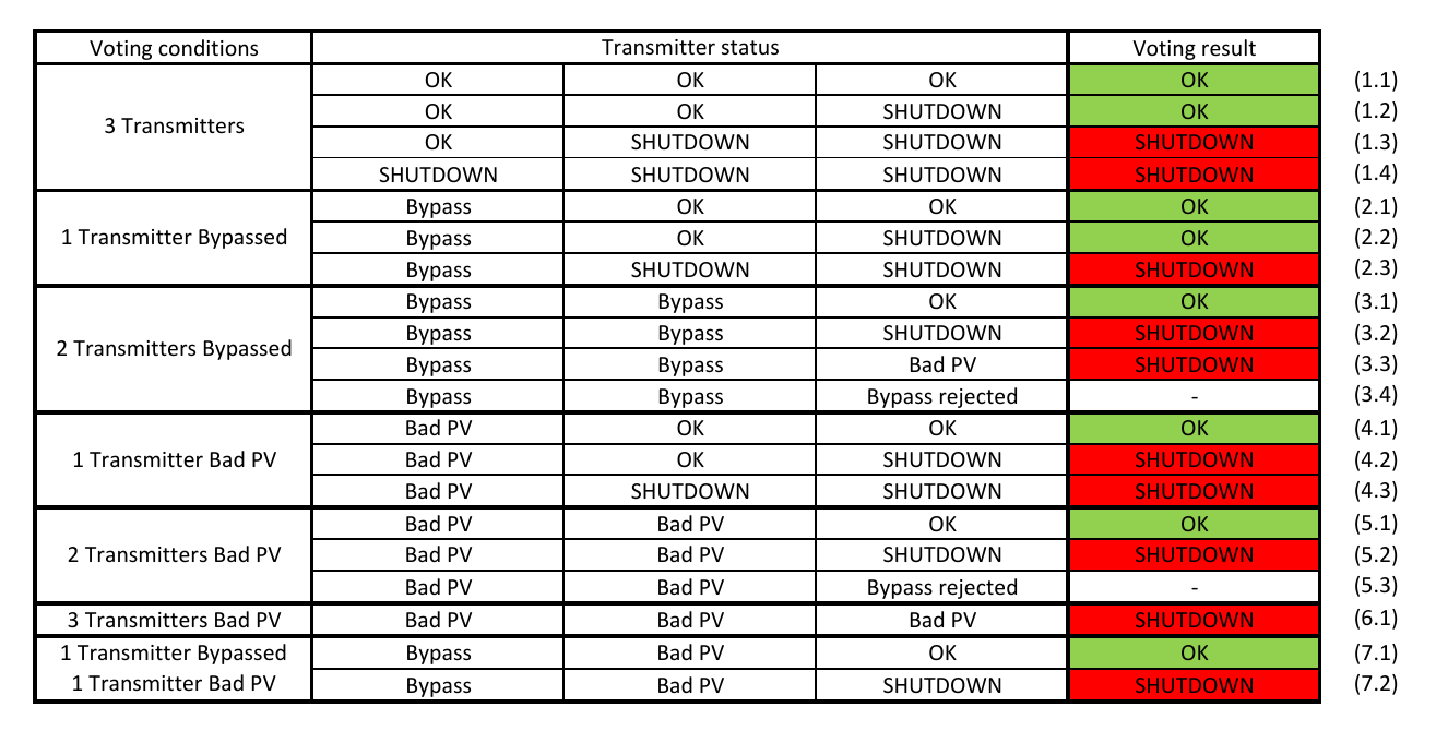
Table 1 - 2oo3 specification
where:
OK - means that transmitter measured value is within a range that is considered as safe/normal working condition. It also means that transmitter measured value is within a range of typically used signals in automation (ex. 0-10V, 4-20mA, etc.).
SHUTDOWN - means that transmitter measured value is outside of a range that is considered as safe/normal working condition. It also means that transmitter measured value is within a range of typically used signals in automation.
Bad PV - means that the transmitter encountered some internal problem and it is out of range of typically used signals in automation. Transmitters can usually detect internal problems and notify about that. Example: let's say that we have a temperature transmitter that is configured to work in a range of 4-20mA. Normally PLC is going to obtain current value and scale it to the proper temperature range. But let's say that temperature probe was disconnected and transmitter is not able to perform measurement. It may set the current to ex. 3.6mA which is below 4mA. Let's say the probe was damaged and its wires where shorted. Transmitter may show 21mA which is above 20mA. Generally, it all depends on transmitter manufacturer, configuration, specification, etc. It is automation engineer responsibility to identify and program those ranges properly.
Bypass - mean that transmitter is excluded from the logic.
3. Specification concerns
According the the point 3.4 of the specification, it is not allowed to bypass the third transmitter if first two are bypassed. Please note that this specification determines the sequence of events and actions. What I mean by that is when You are standing in from of HMI and see that two transmitters are already bypassed, You are not allowed to bypass the third one. That seems reasonable, You have three transmitters in total, You should never bypass all of them because You will be blind for the PV changes.
According to the point 5.3 of the specification, it is not allowed to bypass the third transmitter if first two show bad PV. Again, this specification determines the sequence of events and actions. If You see that two transmitters went bad PV, You are not allowed to bypass the third one. Again, it seems reasonable.
Point 7.x of the specification tells You that You have one transmitter bypassed and one gives Yous bad PV. Questions arise.
Question no. 1:
- How the system should respond to the third transmitter going bad PV? Because if it goes bad PV, You go back to the point 5.3 which says that setting bypass on two bad PV transmitters is not allowed. You previously concluded that You can't go blind so the only action is to remove bypass. But wait, wasn't this bypass set for a reason? There is high chance that this transmitter was bypassed because it went bad PV and You are going to shutdown Your system after removing bypass. There is not much You can do about. Of course You may be lucky because maintenance group fixed the transmitter and didn't have a chance to remove bypass yet.
You may be wondering why I am even considering such cases. It is very unlikely to happen. We have tripple redundancy! By the time we get to this scenerio, maintenance team should had already responded and fixed the problem. Well, You are right. But as automation engineer, You need to make sure that PLC "knows" what to do in all possible scenarios.
Question no. 2:
- Can You bypass third transmitter? Oh yes, and if You do that, You go to the point 3.1 causing system shutdown. Hmm... Why would anyone want to bypass third transmitter in this case?
a) Replacing transmitter. It seems unwise to work on third transmitter before fixing the one with bad PV and/or the one that was already bypassed - it was also bypassed for a reason. It seem reasonable to return the system to normal state before performing any work on third transmitter.
b) Bypassing transmitter because it gives bad PV. Well, if You are considering bypassing it due to bad PV, it is already too late. With two bad PV and bypass You are returning to the Question no. 1 and all its consequences.
c) By mistake. This is the only point I would consider here. You are an automation engineer, You programmed the PLC and You know exactly how does it work. From my experience it is common thing that operators not necessarily know all the nuances of what they are using. For the good of uninterrupted production, I would consider disabling the possibility of bypassing third transmitter in current circumstances.
4. Implementation
There are so many combination of different data that it is easy to get lost. I attempted once to develop the code according the this specification. I used Ladder Logic based on simple NO/NC contacts. It is definately doable. The beginning was not too difficult but the further I went, the more complex and unreadable the code became. Consider to spend some time to think about how You would implement such logic.
Here I would like to introduce an approach that I haven't think about at the first place. It is encapsulated in custom function block.
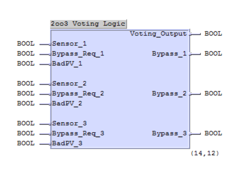
INPUT:
Senson_1, 2, 3 - logical "1" : OK, logical "0" : SHUTDOWN
Bypass_Req_1, 2, 3 - positive pulse that set and reset Bypass_1, 2, 3 accordingly
BadPV_1, 2, 3 - logical "1" : bad PV, logical "0" : PV normal
OUTPUT:
Bypass_1, 2, 3 - logical "1" : bypass active, logical "0" : bypass not active
Voting_Output - result of voting as per specification
4.1 Bypass set/reset/reject logic
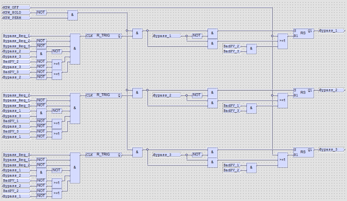
The general idea is that the pulse given on Bypass_Req_X input toggles Bypass_X output. Pulse length is undetermined and the logic needs to be executed only once when pulse appears so R_TRIG is being used. You may think of it as "one controller cycle length" pulse - with the next scan, output of R_TRIG block will be "0". Depending on current Bypass_X state, one of the inputs of RS block is activated. In a result Bypass_X is set ("1") or reset ("0"). There are several additional conditions that implement all what was described in specification concerns.
Rejection of third bypass when two are already set - point 3.4 of the specification.
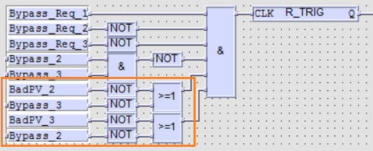
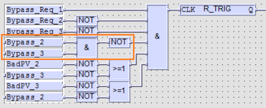
Prevention of unintentional bypass of third transmitter when the first is bypassed and second went bad PV - Question no. 2c.

Prevention of setting any bypass when more than one request is received at the same moment. It is not critical and maybe skipped in Your case. It is shown in this logic because of the way how data were obtained from HMI. Normally, if You replicate this software, run it on real PLC and try to test it, You would not need to think about it because most likely Your HMI would send request one after another. In this particular case, all Bypass_Req_X signals were on Modbus with slow polling time so if an operator set my bypasses fast enough, PLC would get a pulse on more that one input simultaneously. Imagine, You set three bypasses in the order 3,2,1. All three pulses are set at the same time from Modbus perspective and the logic is going to set Bypass_1 and Bypass_2 only (because of the order in which the code is being executed.
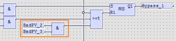
Bad PV removes bypass - Question no. 1.
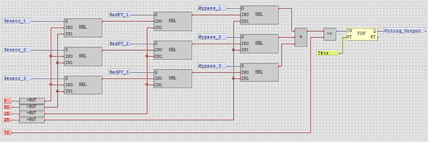
4.2 Voting Logic
We are going to assign different weights for different values of our signals. They were selected experimentally. Let's assign the following:
- Sensor_X - OK as 50
- Sensor_X - SHUTDOWN as 0
- Bypass_X - Activated as 25
- BadPV_X - Activated as 15
In the last column we will sum transmitter weights and compare them with 70 (also experimentally selected). If the result of comparison is grater or equal 70, working conditions are normal. If the result is less that 70, shutdown is executed.
Basically, we have three different signals for each transmitter. They need to be used/interpreted in specific order. From the logic point of view, it is clear that Bypass_X should have the highest priority. We should be able to set a bypass regardless the transmitter status. Then, if we look what's behind Sensor_X signal, we will know that logical "1" (status OK) is when the measured value is within a certain range that we consider as safe/normal working condition. Everything out off that range is considered not safe/normal working conditions - logical "0" (status SHUTDOWN). Pay attention that when the transmitter goes bad PV, it is also out off that range. It means that Sensor_X will be logical "0" (status SHUTDOWN) but specification clearly states what should be the action on case of bad PV. It means that bad PV has a higher priority that Sensor_X status. We have determined the order of priorities which is Sensor_X, Bad_PV_X, Bypass_X and we are going to consider that in the program.
5. Summary
I find this solution of implementation 2oo3 logic pretty elegant. It is not trivial but it shows that thinking out of the box, it is possible to get clear code.
Considering all what was presented, is that all we need to think about? The way of thinking and conclusions seem reasonable but unfortunately, it might not be enough. You may work on safety system for which additional factors should be considered. You might receive some additional requirement from Your client for whom You are programming PLC. It was assumed that You can't go blind but maybe Your client will have a different opinion about that. Generally, as automation engineer, You should think of consulting all Your concerns and program the PLC as requested.